Rockman - Headphone Amp [schematic]
-
darthoverdrive

- Breadboard Brother
I came across these and thought there might be an interest in them. Enjoy
- Attachments
-
 X100 Rev 10.pdf
- X100
- (1.08 MiB) Downloaded 1457 times
-
- Soloist.pdf
- Soloist
- (488.16 KiB) Downloaded 1072 times
-
- X100 IIB Ultralight Pt3.pdf
- X100 IIB Ultralight
- (532.74 KiB) Downloaded 720 times
-
- X100 IIB Ultralight Pt2.pdf
- X100 IIB Ultralight
- (1.1 MiB) Downloaded 679 times
-
- X100 IIB Ultralight Pt1.pdf
- X100 IIB Ultralight
- (1.16 MiB) Downloaded 765 times
-
tschrama

- Breadboard Brother
Information
- Posts: 118
- Joined: 17 Aug 2008, 08:39
- my favorite amplifier: SE El84 DIY .. :D
- Completed builds: Distortion +
Tripple RAT
about 5 Big Muffs
Tubescreamer
JFET simulator
5 Watt SE El84 versions Marshall 2204
5 Watt SE El84 versions Mesa Recto
100W 4xEl34 Mesa Recto - Has thanked: 24 times
- Been thanked: 4 times
Very nice, thank you. BTW...that X100 rev 10 looks like a handdrawn PCB... 
Build your own 50W, three channel, amp in just two days at www.sgravenmade.com
Copyright does not protect facts, ideas, systems, or methods of operation, although it may protect the way these things are expressed. US Copyright Office
Copyright does not protect facts, ideas, systems, or methods of operation, although it may protect the way these things are expressed. US Copyright Office

-
darthoverdrive
- Breadboard Brother
You're welcome. I had to split the one into three parts to get it to upload but it's all there. If anyone has any other Rockman schematics, do post them. Trying to find them on the net is difficult to say the least. I requested some from Dunlop but they don't give them out anymore.Duckman wrote:Thanks for the Soloist!
-
rcustoms

- Resistor Ronker
Information
hi mr overdrive i would like to made a kind of sustainor some parts or something rockman distortion unit ,i think that guy is awesome and very clever .you are interesting in made something like that?darthoverdrive wrote:You're welcome. I had to split the one into three parts to get it to upload but it's all there. If anyone has any other Rockman schematics, do post them. Trying to find them on the net is difficult to say the least. I requested some from Dunlop but they don't give them out anymore.Duckman wrote:Thanks for the Soloist!
-
Yazoo55

- Breadboard Brother
I have been checking out the main board of the Rockman X100 against the schematics. There is a good photo of the main board here: https://www.diystompboxes.com/smfforum/ ... ic=40856.0.
There are some variations, for example the feedback resistor between pins 6 and 7 of IC 2 is 4M7, not 1M. On the whole the resistors are OK. The capacitors are a bit more difficult. You can't see values for a lot of them, and there are capacitors which look more like resistors. Does anybody have a confirmed list of the correct values please?
There are some variations, for example the feedback resistor between pins 6 and 7 of IC 2 is 4M7, not 1M. On the whole the resistors are OK. The capacitors are a bit more difficult. You can't see values for a lot of them, and there are capacitors which look more like resistors. Does anybody have a confirmed list of the correct values please?
-
Yazoo55
- Breadboard Brother
I have gone ahead and started to build this. I have done a version of the main board based on pictures of the board I have found here and elsewhere and I have just etched a modified version of the second board without the echo/reverb.
The main query I have is how do I bias the 2n4339 transistor. There are sample values for the two resistors with a note saying these are factory selected to match the transistor. The resistors are R106 and R107 with sample values of 6.8M and 5.1M respectively.
The main query I have is how do I bias the 2n4339 transistor. There are sample values for the two resistors with a note saying these are factory selected to match the transistor. The resistors are R106 and R107 with sample values of 6.8M and 5.1M respectively.
Hi, I have an x100, if you like I can give you some component values...
-
Yazoo55
- Breadboard Brother
Thanks for the offer. It is the values of the capacitors on the main board that I am especially interested in. I don't need the values for the "echo" board. I appreciate this is a big job so whatever information you can pass on would be gratefully received. If you could check the values of the non-banded capacitors and maybe give me just a couple of the banded ones so I can check against the values I have that would be great.
-
Yazoo55
- Breadboard Brother
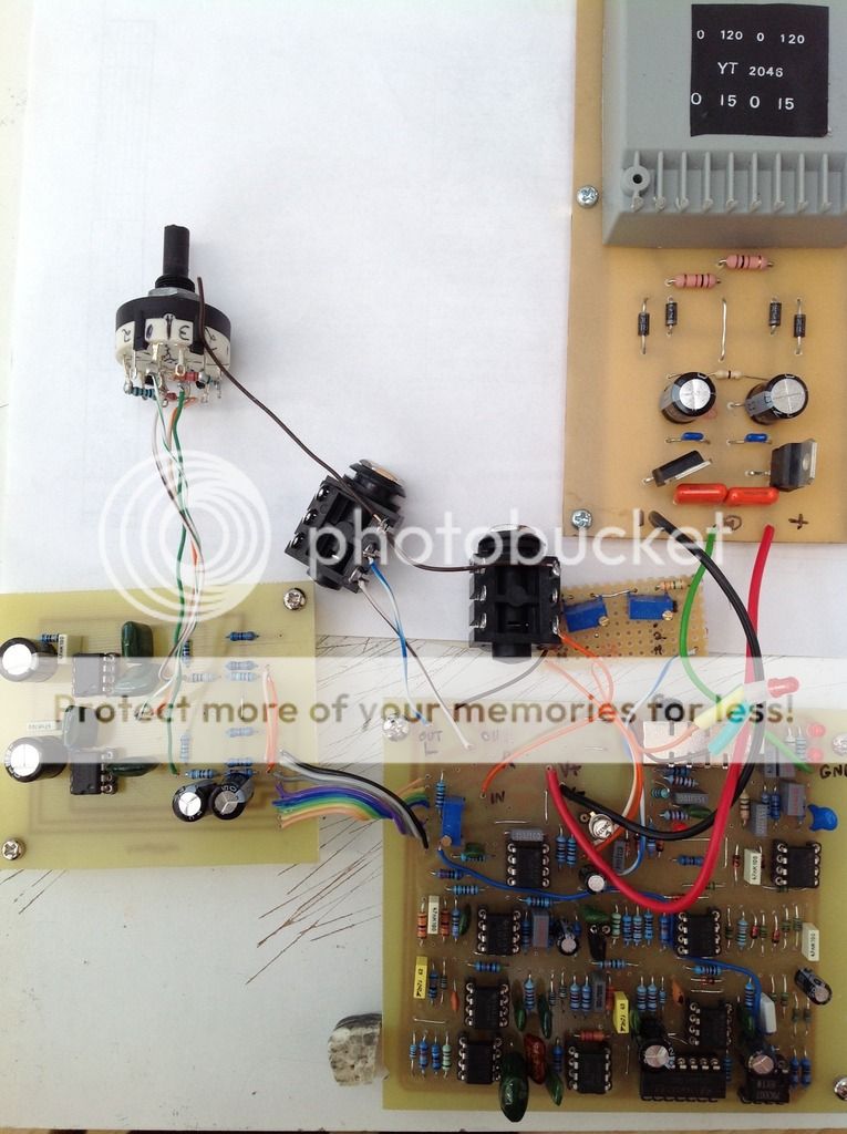
This is a picture of my build. It works but I think it needs tweaking. The compression is a bit too powerful and I get a volume drop on the DIST and EDGE settings. The trimpots in the picture are for adjusting the two resistors which bias the 2n4339 transistor. I used a rotary switch for the volume settings. i had great trouble getting a slide switch for the voice settings but it does work. As usual I charged in and started to build. It was only afterwards that I realised I could have left out the part of the circuit which feeds into the "echo" board. 
-
rcustoms
- Resistor Ronker
Information
awesome work, i have in my table, my pcb version of tom´s smartgate (sustainor model),i hope work ok .Yazoo55 wrote:This is a picture of my build. It works but I think it needs tweaking. The compression is a bit too powerful and I get a volume drop on the DIST and EDGE settings. The trimpots in the picture are for adjusting the two resistors which bias the 2n4339 transistor. I used a rotary switch for the volume settings. i had great trouble getting a slide switch for the voice settings but it does work. As usual I charged in and started to build. It was only afterwards that I realised I could have left out the part of the circuit which feeds into the "echo" board.
[ Image ]
-
Yazoo55
- Breadboard Brother
With Fermusicman's help, it is now working correctly. I had to swap out 5 capacitors and he very kindly checked the correct values for me. Some of the values in the "official" schematics are definitely wrong. I was able to check the resistor values using the photo of the board on the Diystompboxes forum and where the values differed on the official schematic, I went with the ones in the photo. A number of the capacitors also have bands indicating their values - I had never seen capacitors like this before. I have put it all into a 1U rack which had been a KVM switch box. You can pick these up really cheaply off eBay.
There is a lot of compression which can be controlled by picking a bit softer and digging the pick in when you want the compression to really kick in. I have always wanted a Rockman so it was great finding the schematics here. It gave me the impetus to go ahead and build it.
There is a lot of compression which can be controlled by picking a bit softer and digging the pick in when you want the compression to really kick in. I have always wanted a Rockman so it was great finding the schematics here. It gave me the impetus to go ahead and build it.
-
rcustoms
- Resistor Ronker
Information
please post the mistake values,thanksYazoo55 wrote:With Fermusicman's help, it is now working correctly. I had to swap out 5 capacitors and he very kindly checked the correct values for me. Some of the values in the "official" schematics are definitely wrong. I was able to check the resistor values using the photo of the board on the Diystompboxes forum and where the values differed on the official schematic, I went with the ones in the photo. A number of the capacitors also have bands indicating their values - I had never seen capacitors like this before. I have put it all into a 1U rack which had been a KVM switch box. You can pick these up really cheaply off eBay.
There is a lot of compression which can be controlled by picking a bit softer and digging the pick in when you want the compression to really kick in. I have always wanted a Rockman so it was great finding the schematics here. It gave me the impetus to go ahead and build it.
-
Yazoo55
- Breadboard Brother
These are the changed values I used. This is based on the "100 Board Components" list, page 7 of the X100 Rev 10 pdf.
R111 - 12K
R114 - 4M7
R117 - 3K9
R119 - 68K
R144 - 82K
R145 - 200K
R164 - 120K
R166 - 620K
R168 - 30K
C103 - 1N5
C103A - 0.22 uF
C106 - 0.22uF
C107 - 8N2
C108 - 27N
C118 - 0.1uF
C134 - 6N8
C136 22pf
R111 - 12K
R114 - 4M7
R117 - 3K9
R119 - 68K
R144 - 82K
R145 - 200K
R164 - 120K
R166 - 620K
R168 - 30K
C103 - 1N5
C103A - 0.22 uF
C106 - 0.22uF
C107 - 8N2
C108 - 27N
C118 - 0.1uF
C134 - 6N8
C136 22pf
-
rcustoms
- Resistor Ronker
Information
thanks so muchYazoo55 wrote:These are the changed values I used. This is based on the "100 Board Components" list, page 7 of the X100 Rev 10 pdf.
R111 - 12K
R114 - 4M7
R117 - 3K9
R119 - 68K
R144 - 82K
R145 - 200K
R164 - 120K
R166 - 620K
R168 - 30K
C103 - 1N5
C103A - 0.22 uF
C106 - 0.22uF
C107 - 8N2
C108 - 27N
C118 - 0.1uF
C134 - 6N8
C136 22pf
-
Yazoo55
- Breadboard Brother
Just an update. I wasn't happy with the slide switch. It did not always engage positively so I replaced it with 4 interlocking push switches, the kind where as you push one switch, any other pressed switches pop out. I made it easier for myself by just removing the top of the slide switch and soldering wires directly to the contacts. It is much more positive now when you select a voicing.