EH Pocket Metal Muff
-
seniorLoco

- Resistor Ronker
http://www.ehx.com/instructions/Pocket_ ... ctions.pdf
'in Bypass mode, Ouput jack is connected to the Input jack through a buffer."
'in Bypass mode, Ouput jack is connected to the Input jack through a buffer."
"Curiosity may have killed the cat, but it saved the mice, who ate the cheese."
-
ieatyouforbreakfast

- Breadboard Brother
looks like theirs already a blue 3pdt.
i'm pretty sure all electro harmonix are true bypass as of 2007
i'm pretty sure all electro harmonix are true bypass as of 2007
-
allesz
- Cap Cooler
Hallo, I can confirm that the pedal is true bypass. The switch is a 3pdt and, if you take off the battery, the signal pass trough in bypass mode.
I recently opened mine to take some pics of the circuit: a guy in the request folder asked for it. Right now I don't know were the tread has gone, probably I will post here.
I recently opened mine to take some pics of the circuit: a guy in the request folder asked for it. Right now I don't know were the tread has gone, probably I will post here.
Information
- Posts: 5
- Joined: 06 Jun 2011, 07:15
This pedal looks like a real gem, man. True bypass out of the box? 
I play bass, and I'd like to use this pedal more without taking out all of the mids and lows. Are there any mods I can do to give this pedal more life for the bass? I've heard that swapping out the input cap would be great. What else could I change?
I play bass, and I'd like to use this pedal more without taking out all of the mids and lows. Are there any mods I can do to give this pedal more life for the bass? I've heard that swapping out the input cap would be great. What else could I change?
-
allesz
- Cap Cooler
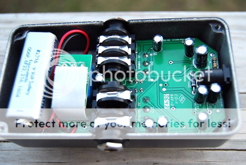
I got some pics.... they are very bad (it can be me or my camera, I suspect me ), hope to be helpful to someone.
I really like this pedal, at first I thought it had too much treble (using it at home) but with the band I find that it just has the ability to cut through.
About modding the thing for bass.... well the idea about the input cap can be a good one; it would be easy if it was not smd, you just can solder a cap in parallel with the existing one (in this way the mod would be easy to undo). being smd I really can't tell.... By the way, which one is the input cap?
- Attachments
-
- IMG_1482.jpg (958.78 KiB) Viewed 2818 times
-
- IMG_1480.jpg (1 MiB) Viewed 2818 times
-
- IMG_1479.jpg (977.09 KiB) Viewed 2818 times
-
- IMG_1478.jpg (999.16 KiB) Viewed 2818 times
-
- IMG_1477.jpg (900.91 KiB) Viewed 2818 times
-
- IMG_1475.jpg (832.48 KiB) Viewed 2818 times
-
- IMG_1474.jpg (958.76 KiB) Viewed 2818 times
-
- IMG_1472.jpg (1014.21 KiB) Viewed 2818 times
-
- IMG_1471.jpg (1.01 MiB) Viewed 2818 times
-
- IMG_1470.jpg (961.19 KiB) Viewed 2818 times
-
- IMG_1468.jpg (1.5 MiB) Viewed 2818 times
Information
- Posts: 5
- Joined: 06 Jun 2011, 07:15
Damn. I've never cracked mine open. It looks pretty dismal. Thanks for the pictures.
Information
- Posts: 5
- Joined: 06 Jun 2011, 07:15
You know what, though? Why exactly don't people want to deal with SMD? I mean... all it means is that we use lots of flux and a few different techniques, right?
If I had the schematic, I would give it a shot.
If I had the schematic, I would give it a shot.
-
CHEEZOR
- Diode Debunker
For me, I don't want to deal with it because I would have to buy a whole bunch of new parts just to try my hand at it.keyofnight wrote:You know what, though? Why exactly don't people want to deal with SMD? I mean... all it means is that we use lots of flux and a few different techniques, right?
If I had the schematic, I would give it a shot.
Information
- Posts: 5
- Joined: 06 Jun 2011, 07:15
I'll try my hand at it. All I need is the schematic. Has anyone got a redrawn schematic of this particular circuit? (Or is it similar enough to the Micro MM or Original MM to get by?)CHEEZOR wrote: For me, I don't want to deal with it because I would have to buy a whole bunch of new parts just to try my hand at it.
-
allesz
- Cap Cooler
Smd components looks difficult to deal with from a diyer point of view.
The pedal works very good though, better than a modern chinese rat for my taste; it has got a lot of basses and with the gain at a minimum it is a good overdrive too.
The last position of the mid switch is really useless (personally I would leave this completely out).
Is there a schemo for the standard metal muff? probably it is the same with just a fixed eq.
Information
- Posts: 5
- Joined: 06 Jun 2011, 07:15
It's not bassy enough for me, but I like what it does with mids (with the scoop turned off).allesz wrote:Smd components looks difficult to deal with from a diyer point of view.
The pedal works very good though, better than a modern chinese rat for my taste; it has got a lot of basses and with the gain at a minimum it is a good overdrive too. The last position of the mid switch is really useless (personally I would leave this completely out). Is there a schemo for the standard metal muff? probably it is the same with just a fixed eq.
I'm probably going to swap out C1 with a higher value cap. I'm not good at understanding schematics, so I can't quite tell what else I should replace in the signal path. I'm sure that simple change will make a world of difference. I'll report back with the results.
-
RnFR
- Old Solderhand
Information
in a circuit this complicated, simply replacing an input cap could have a lot less effect than compared to something like a 2 transistor fuzz. you have to take all of the following coupling caps into consideration as well. in a fuzz face, you only have input and output caps, so it will have a huge difference. with a TB, you have one more in between the two. I haven't seen this schematic, but I'm sure there are several.
"You've converted me to Cubic thinking. Where do I sign up for the newsletter? I need to learn more about how I can break free from ONEism Death Math." - Soulsonic
Blog-APOCALYPSE AUDIO
Blog-APOCALYPSE AUDIO
-
allesz
- Cap Cooler
This is a link to a schemo to start with.
https://www.freestompboxes.org/viewtopic ... 7&start=20
I prefer to spend the damn 40 Euros to buy a factory built one, but it is interesting to look (understand is a big word in my case) how they do it.
Anyway it seems that I should buy a bigger breadboard to try to build this one .
.
https://www.freestompboxes.org/viewtopic ... 7&start=20
I prefer to spend the damn 40 Euros to buy a factory built one, but it is interesting to look (understand is a big word in my case) how they do it.
Anyway it seems that I should buy a bigger breadboard to try to build this one