As I'm sure most of you will know the UV300 is a clone of the old Boss VB1. I'm looking for that crazy whammy wobble sound which I can punch in momentarily during a song and my current options appear to be the Behringer for £20, TC Electronics Shaker for £100 or a VB1 for £300 secondhand (if I can find one)...needless to say, I'm looking at the Behringer
Before I grab one though, I wondered whether any of you guys that have rehoused the Behringer pedals can shed some light on how easy this might be.
I'm thinking that I might be able to replace the existing switch with a more sturdy momentary switch and change the slider switch for a 3 position toggle. Does this sound do-able?
Yep and Yep. I just rehoused the superfuzz pedal. I used a 125 size box and it fit nicely. All I needed to do was replace the contact switch with a momentary spst and then new jacks and dc plug. I replaced all the pots, which was a pain in the butt to get the old ones unsoldered, but you wouldn't have to. On the super fuzz pedal it has, I assume, the same 3 mode switch. I only cared about one setting so I cut off the top of the switch and left it soldered in. It's kind of an odd switch, 3p4t or some non-standard thing that I couldn't find anywhere. Not sure if the UV300 has the same switch or not. I have a UV300 as well but only use it for recording so I haven't opened it up yet.
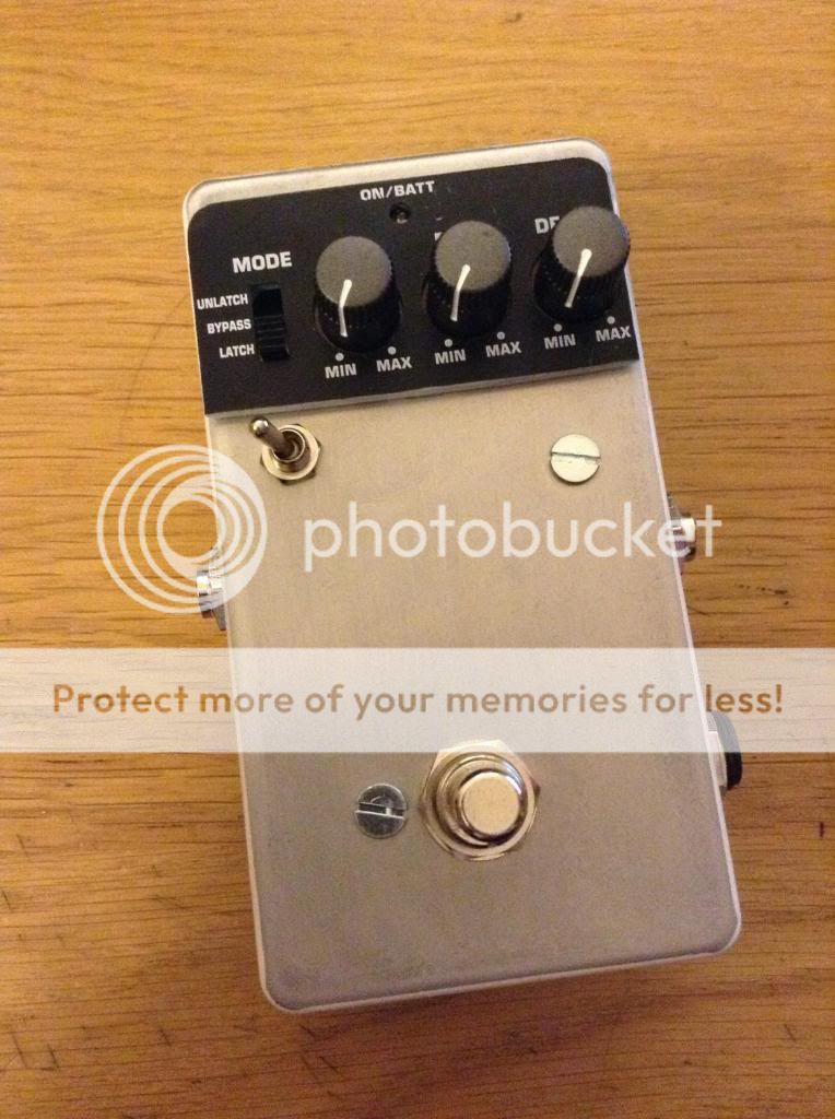
Thread necro, but I did just this using standoffs to keep the existing switch and pots
Fits well into a 125B.
I added an extra switch to parallel a 330nF with the 47nF at c15 for extra slow mode.
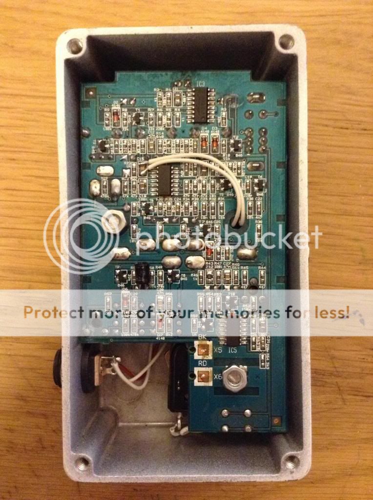
I changed the jacks for Switchcraft-type enclosed jacks, the only pain being the need to relocate a 1uF electro to the SMD side of the pcb, which was pretty easy to do.
Footswitch I simply changed for a SPST momentary from Tayda.
LaceSensor, Did you try to replace any of the pots in this little guy or did you just use the existing ones? I'm doing my best to ID these pots but they're acting a little funky on me.
gandalf wrote:Could I get a step by step guide on how to do this mod slowing the rate down? P.S. I'm a rookie at this stuff
Find C15...
Solder a wire to either side of the C15...
Send those wires to the centre lugs a DPDT switch
Leave one set of the outer lugs "open" = solder nothing to them
Solder a capacitor between 220 - 470nF across the other 2 lugs....i chose 330nF
So that when you throw the switch its either the stock C15 (47nF)...or it parallels another cap to slow the LFO down
tyueda wrote:LaceSensor, Did you try to replace any of the pots in this little guy or did you just use the existing ones? I'm doing my best to ID these pots but they're acting a little funky on me.
I used the existing pots. There was no need to replace them, it would have also been a massive pain in the ass to desolder the pots.
LaceSensor wrote:Thread necro, but I did just this using standoffs to keep the existing switch and pots
Fits well into a 125B.
I added an extra switch to parallel a 330nF with the 47nF at c15 for extra slow mode.
I changed the jacks for Switchcraft-type enclosed jacks, the only pain being the need to relocate a 1uF electro to the SMD side of the pcb, which was pretty easy to do. Footswitch I simply changed for a SPST momentary from Tayda.
no there arent. There is 4 solder points for the tactile switch that is stock but look at the traces, you only need to connect between 1 of each "pair" to activate the bypass
trust me, the pedal works (!) so I know its a SPST switch ....