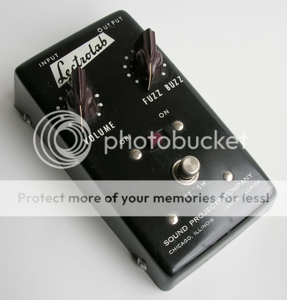
Found this while surfing the web, never heard of this and it looks interesting. It looks like a somewhat different design (not a fuzz face or tonebender at least) thought someone here might be interested. Trying to contribute something here since i lurk all the time. I hope someone can benefit from this.
Very interesting. I acquired a Lectrolab amp a few years back and had never heard of that manufacturer at that time. That fuzzbox is certainly in nice condition.
davidgiandiletti wrote:Found this while surfing the web, never heard of this and it looks interesting. It looks like a somewhat different design (not a fuzz face or tonebender at least) thought someone here might be interested. Trying to contribute something here since i lurk all the time. I hope someone can benefit from this.
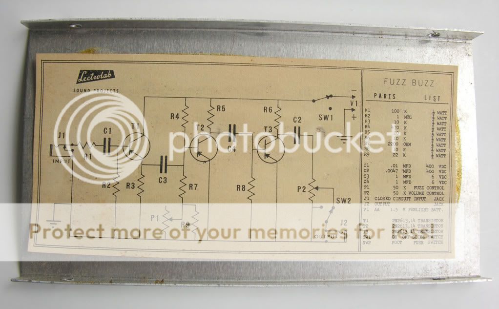
Looks like the Maestro FZ1 to me. It mangles the signal by messing with the bias for the second transistor. My very first fuzz design working a bit like that, but used silicon transistors.... Schematic to follow!
"Why is it humming?" "Because it doesn't know the words!"
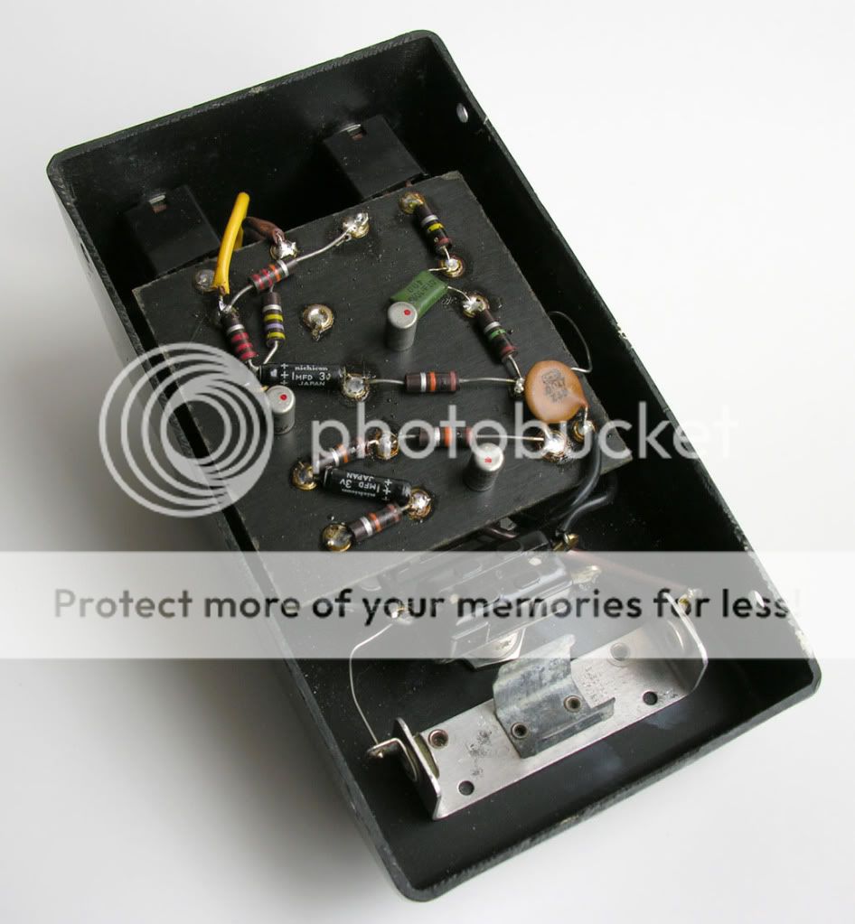
Cups wrote:If this was a boutique builder you cats would have been all over this as being "badly soldered" and "sloppy".
It's almost as if these guys hold $300 boutique dudes who have fancy hakko soldering stations, teflon insulated wire, circuits designed by or based on the work of others, custom through plated PCB's, photographic reference of the work of thousands before them and the internet to read from, ask questions of and source any part or tool under the sun to kind of a different standard than some low wage factory worker trying to cobble together a cheap fad item a few years after the dawn of the transistor.
"You've converted me to Cubic thinking. Where do I sign up for the newsletter? I need to learn more about how I can break free from ONEism Death Math." - Soulsonic