Jen - Jumbo Fuzz [schematic]
-
Kitrae

- Breadboard Brother
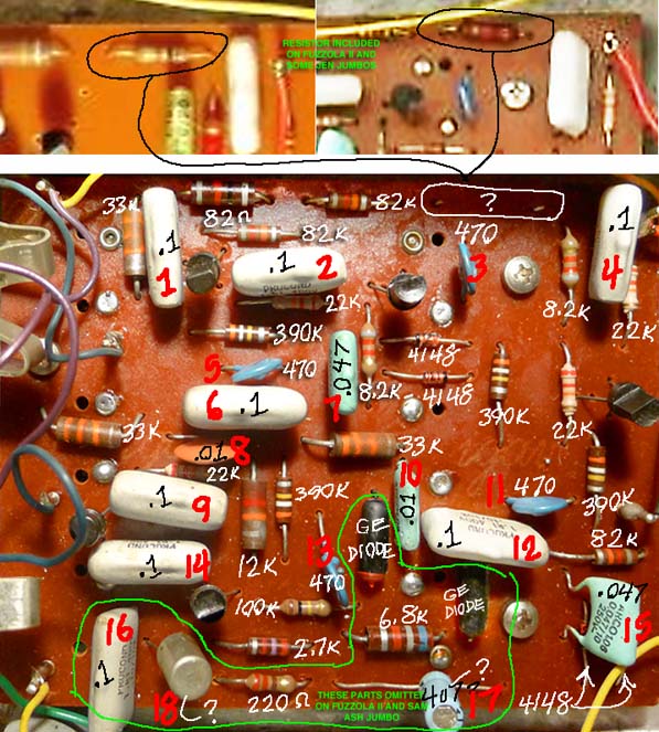
jrod wrote:I've seen a schematic from a traced unit and those values were on there. Though we can't see the trace side in any pics on the net, there is an 82R resistor on the PCB. Also, there are 3-82K resistors on the PCB. The schematic I saw has the 82R from Q1 emitter to ground, and 82K resistors from base to ground on Q1-Q3.
The 4n7 cap was also in the schem I saw, but that cap is not visible in any pics I have seen, so who knows.
To the left of the 12k resistor is a 22k. The 4n7 is the ceramic cap just above that.
I have 5 good photos of this circuit, all very consistent, with the exception that several have parts omitted. There are four 22k resistors on all, and one 12k on all.jrod wrote:Another thing is there was a 12K resistor from the last transistor's collector to +9V. Again, without being able see the trace side we can't be sure, but a 12K resistor does exist on the PCB.
One thing I can't find though is the all the 22K resistors. There are 5 in the original schem. One of which I believe is actually 12K. So, that leaves 4. I only see 3 on the PCB.
It is 6.8k in the gate. The pic on the previous page is shifted in the yellow range, but a simple photoshop hue adjustment show the reds and yellows separated more clearly, making it 6.8. It's 6.8k in one other pic I have too. That schematic looks correct, except for the added 1k, and the fact that the fully populated circuits have 20 caps. That schematic is missing three.jrod wrote:Here's the schematic I copied from the one that was traced. The only difference is they had a 6K8 in the gate circuit but it looks like 68K to me.
Kitrae - Muff junkie
Big Muff Page
http://bigmuffpage.com/
Tonbender Timeline
http://www.bigmuffpage.com/The_Tonebender_Timeline.html
Big Muff Page
http://bigmuffpage.com/
Tonbender Timeline
http://www.bigmuffpage.com/The_Tonebender_Timeline.html
-
Kitrae
- Breadboard Brother
Sorry, 18 caps. Schematic is missing 1. Also, some of the pcbs have 23 resistors. The schematic shows 22, minus the 1k. The extra resistor may be another 100k.
Kitrae - Muff junkie
Big Muff Page
http://bigmuffpage.com/
Tonbender Timeline
http://www.bigmuffpage.com/The_Tonebender_Timeline.html
Big Muff Page
http://bigmuffpage.com/
Tonbender Timeline
http://www.bigmuffpage.com/The_Tonebender_Timeline.html
-
Kitrae
- Breadboard Brother
Kitrae - Muff junkie
Big Muff Page
http://bigmuffpage.com/
Tonbender Timeline
http://www.bigmuffpage.com/The_Tonebender_Timeline.html
Big Muff Page
http://bigmuffpage.com/
Tonbender Timeline
http://www.bigmuffpage.com/The_Tonebender_Timeline.html
-
jrod
- Resistor Ronker
Awesome! Thanks for the info and clarifications, Kitrae!
Ok, I see all four 22k resistors now. So, do you think the gate circuit actually has a 22k in it like in the first schematic posted? Also, the schematic I copied had the 22k in the gate circuit as well.
Ok, I see all four 22k resistors now. So, do you think the gate circuit actually has a 22k in it like in the first schematic posted? Also, the schematic I copied had the 22k in the gate circuit as well.
-
Kitrae
- Breadboard Brother
There are two 10nF caps in the Atelier schemo, total 17 caps. The cap count on the photo above is definitely 18. Maybe that small round ceramic in the middle-left is the other 10nF. I was told by an ebayer that the ceramic was marked 4u7, but I'm doubting that now. The blue cap to the right of the vertical GE diode is definitely one of the 10nF's because I can see the value in another photo, and it makes sense that the 4.7 would the polarized electro at the bottom. The cap to the left of the 220Ω resistor at the bottom is the 18th, and it appears in three of the pix I have, but I don't think that is accounted for in any schematic so far.jrod wrote:I'm only seeing 17 caps.Kitrae wrote:Sorry, 18 caps. Schematic is missing 1.
1 - Electro - 4u7?
8 - 100nF
2 - 47nF
1- 10nF
1 - 4.7nF
4 - 47pF
Hard to say without seeing the trace side, but I'm not exactly sure what the 22k is doing in the gate circuit on the versions without the other gate components. There are four 22k's in each version, and the versions without the gate parts still include one of the two extra transistors from the gate. The 22k must be for the collector of that transistor.jrod wrote:Awesome! Thanks for the info and clarifications, Kitrae!
Ok, I see all four 22k resistors now. So, do you think the gate circuit actually has a 22k in it like in the first schematic posted? Also, the schematic I copied had the 22k in the gate circuit as well.
I'm hoping to have one of these in about a week, so I'll know for sure. It's really the only other BMP clone from the 70's I don't have.
Kitrae - Muff junkie
Big Muff Page
http://bigmuffpage.com/
Tonbender Timeline
http://www.bigmuffpage.com/The_Tonebender_Timeline.html
Big Muff Page
http://bigmuffpage.com/
Tonbender Timeline
http://www.bigmuffpage.com/The_Tonebender_Timeline.html
-
jrod
- Resistor Ronker
Thanks!
Looking forward to seeing your findings when you get hold of a unit!
I think the part that you have labeled as cap #18 is actually the germanium transistor in the gate circuit.
Looking forward to seeing your findings when you get hold of a unit!
I think the part that you have labeled as cap #18 is actually the germanium transistor in the gate circuit.
-
Kitrae
- Breadboard Brother
There are two Ge diodes in the gate, and they are black cased with red ends in the photo above. They are large glass cased diodes in some of the other photos I have, same locations. Part 18 looks like an electro in one circuit photo I have, and like a polystyrene or film cap in another, so I'm sure that's just a cap. Look at the circuit with all the large light blue caps on the previous page. It definitely looks like a cap there too.
Kitrae - Muff junkie
Big Muff Page
http://bigmuffpage.com/
Tonbender Timeline
http://www.bigmuffpage.com/The_Tonebender_Timeline.html
Big Muff Page
http://bigmuffpage.com/
Tonbender Timeline
http://www.bigmuffpage.com/The_Tonebender_Timeline.html
-
D-Day

- Mojo Book Buster
I'm not going to go through and click the thanks button for every post but I really appreciate what you guys are up to. The Big Muff is my favorite distortion circuit ever and this thread is exciting times 
-
Kitrae
- Breadboard Brother
Confirmed that a Jumbo Fuzz is on its way to me, but unfortunately it's one without all of the gate components. I think once we see the trace side all will become clear.
Kitrae - Muff junkie
Big Muff Page
http://bigmuffpage.com/
Tonbender Timeline
http://www.bigmuffpage.com/The_Tonebender_Timeline.html
Big Muff Page
http://bigmuffpage.com/
Tonbender Timeline
http://www.bigmuffpage.com/The_Tonebender_Timeline.html
-
jrod
- Resistor Ronker
Sweet!Kitrae wrote:Confirmed that a Jumbo Fuzz is on its way to me, but unfortunately it's one without all of the gate components. I think once we see the trace side all will become clear.
Kitrae, before you take apart your new Jumbo Fuzz, here's some pics of mine I took apart earlier this week.
Its the non-gate version as well and its one noisy f#cker indeed.


If you guys have any question or need more pics, just ask
Its the non-gate version as well and its one noisy f#cker indeed.
If you guys have any question or need more pics, just ask
-
Kitrae
- Breadboard Brother
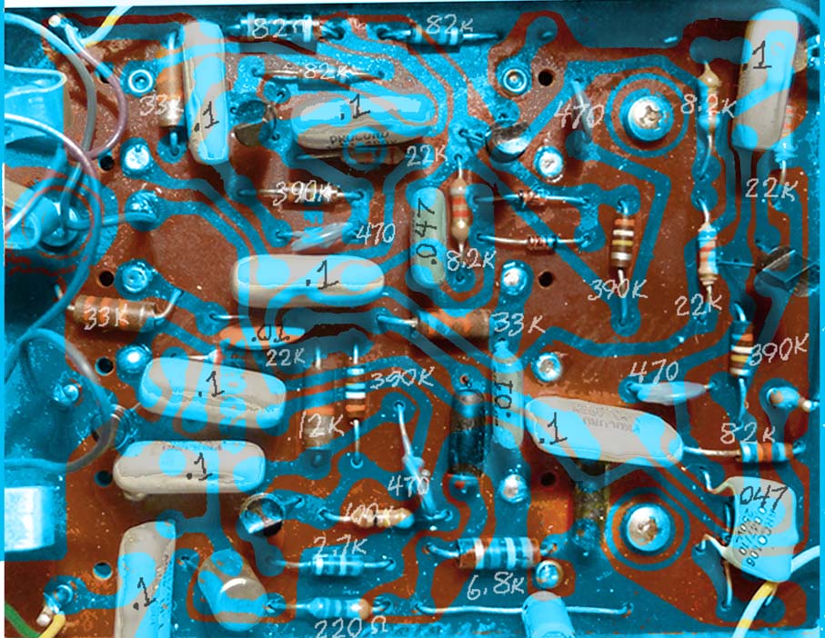
Perfect! I'll look it over later today, but here is a quick trace overlay.
Kitrae - Muff junkie
Big Muff Page
http://bigmuffpage.com/
Tonbender Timeline
http://www.bigmuffpage.com/The_Tonebender_Timeline.html
Big Muff Page
http://bigmuffpage.com/
Tonbender Timeline
http://www.bigmuffpage.com/The_Tonebender_Timeline.html
-
Kitrae
- Breadboard Brother
Kitrae - Muff junkie
Big Muff Page
http://bigmuffpage.com/
Tonbender Timeline
http://www.bigmuffpage.com/The_Tonebender_Timeline.html
Big Muff Page
http://bigmuffpage.com/
Tonbender Timeline
http://www.bigmuffpage.com/The_Tonebender_Timeline.html
-
Kitrae
- Breadboard Brother
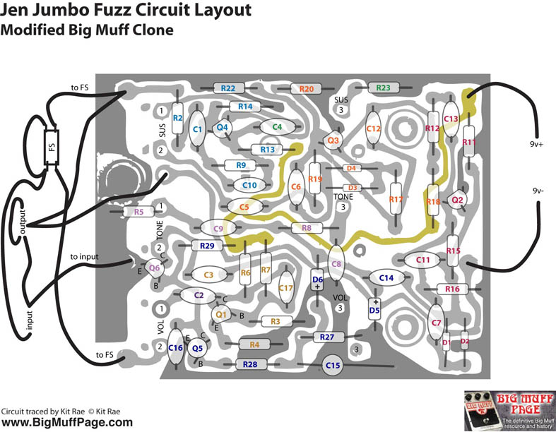
OK, here it is. That extra cap IS a GE transistor (you are right jrod). I guess I was just hoping there was something more to the tone section and gate, but it's not really any different than what was posted before. Sinner's layout is basically correct, except the 12k on his layout (R19) should be 22k, and the missing 6.8k resistor where D6 goes to ground. That 6.8k IS missing from a few of these Jumbos though. The Atelier Musiques schemo is close too, just missing a few parts, and a few wrong values.
The extra resistor at the top right of the board that is missing on most of these is the 1k from the sustain pot, just like on a standard Big Muff. Apparently it was only used on the Fuzzola II version.
The only thing that baffles me is why that 22k (R29 on my schemo) in the noise gate was left in for the versions without the gate. It does absolutely nothing, unless there is a jumper on the back of the pcb for some of those to actually connect the other lead on the resistor back to the circuit. I need to see the trace side of a few more to know for sure, but on bluesbreaker64's and my Jumbo, it dead ends.
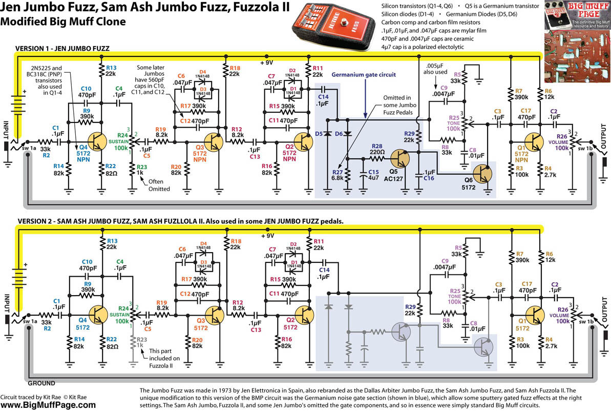
Kitrae - Muff junkie
Big Muff Page
http://bigmuffpage.com/
Tonbender Timeline
http://www.bigmuffpage.com/The_Tonebender_Timeline.html
Big Muff Page
http://bigmuffpage.com/
Tonbender Timeline
http://www.bigmuffpage.com/The_Tonebender_Timeline.html
-
sinner
- Old Solderhand
Information
- Posts: 4709
- Joined: 06 Nov 2008, 17:16
- Location: ...no more
- Has thanked: 1031 times
- Been thanked: 909 times
Great Thanks
I just finished stripboard for this - 23 holes long, 14 wide, so will fit into Hammond 125B enclosure. Couldn't do it any smaller caring for component raster (5mm caps, and 1/4 resistors). I'll match it to your schematic (the one with gate circuity) and post it over weekend. Time to hit the hay
I just finished stripboard for this - 23 holes long, 14 wide, so will fit into Hammond 125B enclosure. Couldn't do it any smaller caring for component raster (5mm caps, and 1/4 resistors). I'll match it to your schematic (the one with gate circuity) and post it over weekend. Time to hit the hay
-
Kitrae
- Breadboard Brother
Did it also have white box caps?
Kitrae - Muff junkie
Big Muff Page
http://bigmuffpage.com/
Tonbender Timeline
http://www.bigmuffpage.com/The_Tonebender_Timeline.html
Big Muff Page
http://bigmuffpage.com/
Tonbender Timeline
http://www.bigmuffpage.com/The_Tonebender_Timeline.html
-
sinner
- Old Solderhand
Information
- Posts: 4709
- Joined: 06 Nov 2008, 17:16
- Location: ...no more
- Has thanked: 1031 times
- Been thanked: 909 times