Colorsound - Dipthonizer  [schematic]

Discussion regarding early stompbox technology: 1960-1975 Please keep discussion focused and contribute what info you have...
User avatar
dcountry13
Information
Posts: 36
Joined: 07 Mar 2008, 02:47
Has thanked: 9 times
Been thanked: 7 times

Post by dcountry13 »

If you notice there are 2 ground traces running around the outer edge of board. If you look at the In and Out Jacks, the Rings are connected with a short trace. The Sleeve of the Out is connected to that far outer trace and the The Sleeve of the IN is connected to the ground trace that has the outer solder pad and goes to the switch. I soldered the trace just to confirm all grounds were connected. Probably overkill, if the jacks are mounted (wired) correctly.

As far as your problem goes....
you stated you heard sweeping, with the touching of the wrong trace? So it sounds like the circuit is doing it's thing. If you are having issues with bypass, too, it sounds like the wiring.

As far as the wiring::
dcountry13 wrote:Here is the verified layout that worked for me. The 5.1 Zeners look like the diodes (Red w/ Yellow line showing orientation) have Blue "Z" indicators. The values may be debatable as with any reverse engineering job goes because of discrepancies in sources.

I used toneman's numbered board, the schematic, boris' hand-drawn layout & wiring, my7of9's PCB clean-up & etching skills and Geekmacdaddy's BOM & inspiration.

Image

I wired it using the usual 3PDT method outlined here (Offboard wiring #5 http://www.tonepad.com/getFile.asp?id=76).
If you are looking at my parts layout the solder pads across the bottom, left to right, 1-6 are:
1. Output Jack.
2. Effects/Circuit/Board Input.
3. 18 volt power supply.
4. Input Jack.
5. Effects/Circuit/Board Output.
6. Ground.
So the +9V would go to Pin 3 going Left-to-Right, Looking at the board Solder-Side Down.
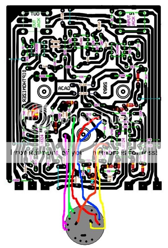
The Battery Ground would go to Pin 6 going Left-to-Right, Solder-Side Down.

See if my pics help. Black is Ground, Red is +9v. I soldered the Ground for the Battery/18v Source (9v to 18V charge pump in my case) to the component side of Pin 6 and the solder side goes to the Switch, to control the LED.

Image

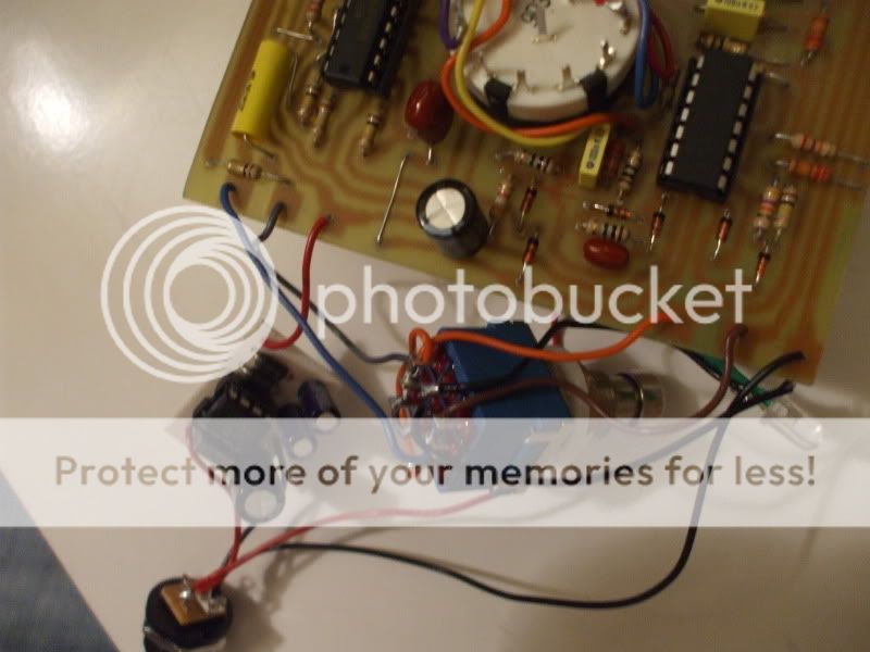
Can you send pics of your wiring (jacks, too) and the wiring diagram?

I'd like too see another working one.

User avatar
bjlevine
Information
Posts: 17
Joined: 30 Jun 2010, 14:42

Post by bjlevine »

I heard the sweeping when I touched the battery ground to the outer ground trace on the board. I'll try running a jumper between the two ground traces, like you have it, and see what I get. Thanks.

User avatar
bjlevine
Information
Posts: 17
Joined: 30 Jun 2010, 14:42

Post by bjlevine »

One of the questions I have is that I am trying to use standard DC input and Battery wiring, with the negative from the battery going to the input plug ring, per this diagram:

Image

But I've never used theser kind of switches before. Seems like when the jack is inserted, the connection between the two middle connectors on the imput jack is opened. Moreover, this connection on the board seems to only run between the input and output connectors. So I really don't know where I should wire the negative from the battery so that it breaks the circuit when I remove my input cable from the jack (does this make sense?). Any ideas?

Update: after doing some reading, it seems like if I wire my negative to the 2nd outside connector on the input jack, it should then connect to the ground when the plug is connected, bridging the sleeve and tip connectors. I'll give this a try tonight.

User avatar
bjlevine
Information
Posts: 17
Joined: 30 Jun 2010, 14:42

Post by bjlevine »

Okay, some success. I ran a jumper across the "shield" pins on the input plug and then wired the battery ground to the inner "ring" pin, and voila, I have Dipthonizer. Well, it seems to be working on the second setting of the rotary switch, but the other three settings have really bad hiss.

Here's my input plug wiring:
Image

And some audio samples:
http://www.animecollectibles.com/dip/silentwings.mp3
http://www.animecollectibles.com/dip/theancient.mp3

User avatar
bjlevine
Information
Posts: 17
Joined: 30 Jun 2010, 14:42

Post by bjlevine »

I still have the hiss issue to deal with, but here's a picture of the unit in its case (1590D):

Image

User avatar
soulfistication
Information
Posts: 1
Joined: 24 Sep 2010, 23:47

Post by soulfistication »

Hi there everyone. Please bear with a newbie on his first post to this website forum, especially if I am not adhering to proper protocols out of ignorance. :hmmm:

I came across this thread and was hoping to post an inquiry about CS Diptho repair/build. I have one of these and want to look into getting it cloned because I would prefer to put something usable onto my pedalboard and not worry about the damage. Also, my teeth have been falling out from overusing my talkbox (ok, just kidding, I'm not quite that old yet!). Due to its age I am not sure if my CS Diptho is even working properly (sweep control seems weak and non-functional). Is it typical on these posts to solicit repair or clone work, or is that inappropriate? :slap: I don't want to seem to be speaking out of turn, but I am not technically inclined, just a guitar player looking for the right tone, and this seems to be a well-informed group with great technical expertise. Also, it seems that a clone has an advantage to the extent that 18V adapter might be workable (I hate having battery-powered items on my board) and/or to the extent that expression pedals or custom trimpots might add to the tone possibilities and tweakability sluttage. :lol:

So, if there is someone out there who is willing to build a clone for me and/or consider repairing an existing original, I would be interested in getting in touch. I note that this post also contains questions about the A/DA Harmony Synth, for which I am happy to provide photos of my original if someone is looking into building a clone of that as well (god bless you if you can pull it off, it is a piece of technical work from what I can see, and loads of fun to mess around with). :secret:

Thank you sincerely for your consideration, and also for your efforts in creativity and engineering.
soulfisticationATyahooDOTcom

User avatar
Greenmachine
Cap Cooler
Information
Posts: 616
Joined: 31 Aug 2008, 17:59
my favorite amplifier: Fender Blackface Deluxe Reverb
Completed builds: Electra Distortion
Roger Mayer Octavia
Klon Centaur (Bajaman/Soulsonic)
DOD 440 Envelope Filter
MXR Phase 90
DOD FET Preamp
Dallas Arbiter Fuzz Face
Soulsonic Hunny Bunny Overdrive
BYOC Analog Delay
Craig Anderton Headphone Amp
Anderton Mini Amp
Bajaman Real Tube Overdrive
Fender Deluxe 5E3 with Tone Stack Mod.
Fender Princeton 5F2-a
Keen Neovibe
Aquapuss Delay
Anderton AMS-100 Guitar Synth (abandoned)
DOD 280 Compressor
Weird Sound Generator
Beavis Audio Noisy Cricket
80's Rat
ROG Thor
Big Muff
Green Ringer
Shin-Ei Fuzz
MXR Dynacomp
COT50
Really Cheap Compressor
Location: Jersey City, NJ
Has thanked: 87 times
Been thanked: 17 times
Contact:

Post by Greenmachine »

soulfistication wrote: the A/DA Harmony Synth, for which I am happy to provide photos of my original if someone is looking into building a clone of that as well
You don't even have to ask. Most of us here are drooling idiots for detailed photos of vintage pedals. *slurp* :shock:

(not to say that I'm personally any good at tracing/making schems :oops: )
"[Y]ou want sketchy, dude? I breadboard on a door." -- RnFR, 2011
"This amp is freakin loud, like crazy, I'm going to kill pets loud." -- mich, 2011

User avatar
bjlevine
Information
Posts: 17
Joined: 30 Jun 2010, 14:42

Post by bjlevine »

Since my memory sucks, I made a wiring diagram for True Bypass wiring for the Dipthonizer, using the Tonepad wiring diagram. Please correct anything you see wrong.

Image

User avatar
borislavgajic
Opamp Operator
Information
Posts: 1542
Joined: 27 Feb 2008, 14:23
Completed builds: ...script phase90,ETI phaser,Ross phaser,mutronC200,vox wah,WH10,FW-3,mutronIII,DrQuack,Penfoldautowah,Tubezipper,
Dipthonizer,seekwah,Talkingpedal,morleywha
...soulpreacher,dynacomp,compulator
...buzzaround,fuzzfactory,screwdriver,sho,superdouper,St-9,RogerMayer octavia,Tychobrahe octavia,paralelluniverse,string damper,slowgear
...CE-2,ibanez fL301,EH theCloneTheory
EHX bassmicrosynth,EHX EnglishMuffin,Tube Phaser,springtubereverb ,greyDOD,FulldriveII mosfet,OCD,VOX repeat percussion,RingStinger,Meatball,12stage phaser....
Location: Sombor , Serbia
Has thanked: 131 times
Been thanked: 281 times

Post by borislavgajic »

thank you for doing this :thumbsup

Boris

User avatar
bjlevine
Information
Posts: 17
Joined: 30 Jun 2010, 14:42

Post by bjlevine »

And while I'm at it, I've updated the bottom copper layout image, so that the input shield connectors are tied and added holes, one by the input shield for the power connector ground and one by the inner input ring connector for the battery snap ground.

http://www.animecollectibles.com/dip/Di ... pdated.tif

I've been playing around with Eagle. I would love to get this down to a 4" x 3" board, but its really tight. I think if I get rid of the Neutrik connectors and just go with standard jack connectors, I should have room.

Dang, but I'm hooked on this stuff now.

User avatar
bjlevine
Information
Posts: 17
Joined: 30 Jun 2010, 14:42

Post by bjlevine »

Okay, here's an early mockup of the board (using Eagle) that is 4" x 3.2". Using standard 1/4" connectors rather than the Neutrik to save space on the board.

Layout:
http://www.animecollectibles.com/dip/di ... -small.tif

Bottom Copper:
http://www.animecollectibles.com/dip/di ... bottom.tif

I'm going to try running one of these off and see how it works, but I thought I'd post it to see if anyone can spot any glaring errors that I missed.

User avatar
gigelmargel
Resistor Ronker
Information
Posts: 330
Joined: 16 Jul 2007, 20:57
Has thanked: 111 times
Been thanked: 23 times

Post by gigelmargel »

hello,

first, many thanks to boris and to all the other people which worked at this wonderful project!

i've just finished to build one, but it works only as a fuzz...no sweep :(
i've tested all the ic's and are ok...i didn't use onboard jacks and i wired it directly (no bypass yet)...all the ic's are "feeded"... :scratch:

can anyone who built it successfully to post the volatges, please?

thank you very much!

User avatar
borislavgajic
Opamp Operator
Information
Posts: 1542
Joined: 27 Feb 2008, 14:23
Completed builds: ...script phase90,ETI phaser,Ross phaser,mutronC200,vox wah,WH10,FW-3,mutronIII,DrQuack,Penfoldautowah,Tubezipper,
Dipthonizer,seekwah,Talkingpedal,morleywha
...soulpreacher,dynacomp,compulator
...buzzaround,fuzzfactory,screwdriver,sho,superdouper,St-9,RogerMayer octavia,Tychobrahe octavia,paralelluniverse,string damper,slowgear
...CE-2,ibanez fL301,EH theCloneTheory
EHX bassmicrosynth,EHX EnglishMuffin,Tube Phaser,springtubereverb ,greyDOD,FulldriveII mosfet,OCD,VOX repeat percussion,RingStinger,Meatball,12stage phaser....
Location: Sombor , Serbia
Has thanked: 131 times
Been thanked: 281 times

Post by borislavgajic »

measure voltages on pins 5 of 3080 ICs........while playing guitar they should dance while you play..........if yes,error is in blend pot circutry........if there is no swinging voltages on pins 5...then error is to be find around roto switch sensitivity pot....

hope this helps :thumbsup

User avatar
gigelmargel
Resistor Ronker
Information
Posts: 330
Joined: 16 Jul 2007, 20:57
Has thanked: 111 times
Been thanked: 23 times

Post by gigelmargel »

borislavgajic wrote:measure voltages on pins 5 of 3080 ICs........while playing guitar they should dance while you play..........if yes,error is in blend pot circutry........if there is no swinging voltages on pins 5...then error is to be find around roto switch sensitivity pot....

hope this helps :thumbsup
Thx a lot Boris!
Now I am out of town, but Sunday night, when I will be back home, this will be the first thing that I will made :)

User avatar
gigelmargel
Resistor Ronker
Information
Posts: 330
Joined: 16 Jul 2007, 20:57
Has thanked: 111 times
Been thanked: 23 times

Post by gigelmargel »

After an hour of debugging, I found a very small solder joint near a LM324...now it's working very fine...thx a lot Boris for this wonderful project!

On the initial schematic I saw that the cap parellel with the clipping diodes is 2.2nF, but you recommended 200 pf (i used 220pF)...why?
How affects the 2.2M the sound? And for what you replaced the 180K with 340K?

Best regards,
Radu

User avatar
borislavgajic
Opamp Operator
Information
Posts: 1542
Joined: 27 Feb 2008, 14:23
Completed builds: ...script phase90,ETI phaser,Ross phaser,mutronC200,vox wah,WH10,FW-3,mutronIII,DrQuack,Penfoldautowah,Tubezipper,
Dipthonizer,seekwah,Talkingpedal,morleywha
...soulpreacher,dynacomp,compulator
...buzzaround,fuzzfactory,screwdriver,sho,superdouper,St-9,RogerMayer octavia,Tychobrahe octavia,paralelluniverse,string damper,slowgear
...CE-2,ibanez fL301,EH theCloneTheory
EHX bassmicrosynth,EHX EnglishMuffin,Tube Phaser,springtubereverb ,greyDOD,FulldriveII mosfet,OCD,VOX repeat percussion,RingStinger,Meatball,12stage phaser....
Location: Sombor , Serbia
Has thanked: 131 times
Been thanked: 281 times

Post by borislavgajic »

gigelmargel wrote:After an hour of debugging, I found a very small solder joint near a LM324...now it's working very fine...thx a lot Boris for this wonderful project!

On the initial schematic I saw that the cap parellel with the clipping diodes is 2.2nF, but you recommended 200 pf (i used 220pF)...why?
How affects the 2.2M the sound? And for what you replaced the 180K with 340K?

Best regards,
Radu

you are welcome.......
2n2 gives muddy tone........you can try to solder that value and see........
resistor change solved volume drop ....but you can see how do you like sound with original values :thumbsup

Glad you find error in your build....!
cheers

Boris

User avatar
gigelmargel
Resistor Ronker
Information
Posts: 330
Joined: 16 Jul 2007, 20:57
Has thanked: 111 times
Been thanked: 23 times

Post by gigelmargel »

borislavgajic wrote:
gigelmargel wrote:After an hour of debugging, I found a very small solder joint near a LM324...now it's working very fine...thx a lot Boris for this wonderful project!

On the initial schematic I saw that the cap parellel with the clipping diodes is 2.2nF, but you recommended 200 pf (i used 220pF)...why?
How affects the 2.2M the sound? And for what you replaced the 180K with 340K?

Best regards,
Radu

you are welcome.......
2n2 gives muddy tone........you can try to solder that value and see........
resistor change solved volume drop ....but you can see how do you like sound with original values :thumbsup

Glad you find error in your build....!
cheers

Boris
Thank you very much again Boris!

I've asked you all that things because mine sounds good, but not as in the demo from youtube posted above (I have an squier affinity)...the 10K sweep pot seems to act only on some portions...and, with the 220pF, the fuzz part seems to sound too treblish...so more experiments needed :)

Best regards,
Radu

User avatar
borislavgajic
Opamp Operator
Information
Posts: 1542
Joined: 27 Feb 2008, 14:23
Completed builds: ...script phase90,ETI phaser,Ross phaser,mutronC200,vox wah,WH10,FW-3,mutronIII,DrQuack,Penfoldautowah,Tubezipper,
Dipthonizer,seekwah,Talkingpedal,morleywha
...soulpreacher,dynacomp,compulator
...buzzaround,fuzzfactory,screwdriver,sho,superdouper,St-9,RogerMayer octavia,Tychobrahe octavia,paralelluniverse,string damper,slowgear
...CE-2,ibanez fL301,EH theCloneTheory
EHX bassmicrosynth,EHX EnglishMuffin,Tube Phaser,springtubereverb ,greyDOD,FulldriveII mosfet,OCD,VOX repeat percussion,RingStinger,Meatball,12stage phaser....
Location: Sombor , Serbia
Has thanked: 131 times
Been thanked: 281 times

Post by borislavgajic »

and Radu.....some pictures would be great!!!!!! to see how it looks :blackeye :thumbsup

Boris

User avatar
gigelmargel
Resistor Ronker
Information
Posts: 330
Joined: 16 Jul 2007, 20:57
Has thanked: 111 times
Been thanked: 23 times

Post by gigelmargel »

borislavgajic wrote:and Radu.....some pictures would be great!!!!!! to see how it looks :blackeye :thumbsup

Boris
I will try to make some pictures after I will finished it and I will put it in a box...I hope that in the next days I will have enough time for it :)

Anyway, the look of my stompboxes isn't my strong point :(

User avatar
borislavgajic
Opamp Operator
Information
Posts: 1542
Joined: 27 Feb 2008, 14:23
Completed builds: ...script phase90,ETI phaser,Ross phaser,mutronC200,vox wah,WH10,FW-3,mutronIII,DrQuack,Penfoldautowah,Tubezipper,
Dipthonizer,seekwah,Talkingpedal,morleywha
...soulpreacher,dynacomp,compulator
...buzzaround,fuzzfactory,screwdriver,sho,superdouper,St-9,RogerMayer octavia,Tychobrahe octavia,paralelluniverse,string damper,slowgear
...CE-2,ibanez fL301,EH theCloneTheory
EHX bassmicrosynth,EHX EnglishMuffin,Tube Phaser,springtubereverb ,greyDOD,FulldriveII mosfet,OCD,VOX repeat percussion,RingStinger,Meatball,12stage phaser....
Location: Sombor , Serbia
Has thanked: 131 times
Been thanked: 281 times

Post by borislavgajic »

:wink: :thumbsup

Post Reply