HH electronics - Clockwork Concubine [schematic]
Anybody figure out how to make the 7 pin plug and where they cut got the parts?
-
Dirk_Hendrik

- Old Solderhand
Information
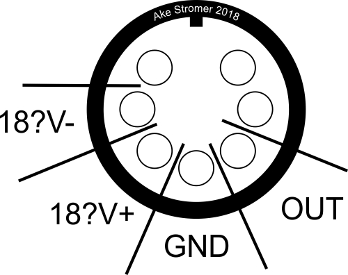
Obtaining a 7 pin DIN connector should not be that hard. Same for a chassis mount as the contra plug. As for the supply voltage, use anything over 13.6 volt and the bitch should start to sing. To get the lights on will take a higher voltage though
I think I've finally figure it out.
View from front.
https://3.bp.blogspot.com/-nSq20dKQ0AU/ ... clkwrk.jpg
I'll try to make more sense of it soon.
View from front.
https://3.bp.blogspot.com/-nSq20dKQ0AU/ ... clkwrk.jpg
I'll try to make more sense of it soon.
Hey there, big thanks to Ake and Dirk for the information, don’t think I’d have got so this far so quickly without it 
I brought one last week for £20 in a junk shop and didn’t really know much about it. I’ve now run it off my bench supply and had a listen! All works good…
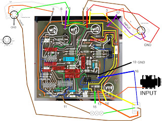
I was puzzled by what Dirk has tagged as V_OSC net and the third Zener, which made no sense to me as there was already a Zener and a negative voltage for the -ve of the split-rail.
On taking mine apart I could see that there Is no D2, and it looks like it was never fitted, I have what looks like a factory fitted mod wire soldered from D4 to the -ve of C10. So effectively just joins together nets VDD and V_OSC on Dirk's schematic. I wonder if I have a later unit and they realised the devices didn’t draw enough VDD current to justify having two negative Zeners?
My plan now is to internally fit a small buck/boost split rail module, feed a supply the rails directly with properly regulated DC, drill out and fit an 1/4 output jack and a normal +9vdc Input. Hell, I might even buy some 1/2w LEDs to make the logo light up as all those filament bulbs in mine gave up long ago....

I brought one last week for £20 in a junk shop and didn’t really know much about it. I’ve now run it off my bench supply and had a listen! All works good…
I was puzzled by what Dirk has tagged as V_OSC net and the third Zener, which made no sense to me as there was already a Zener and a negative voltage for the -ve of the split-rail.
On taking mine apart I could see that there Is no D2, and it looks like it was never fitted, I have what looks like a factory fitted mod wire soldered from D4 to the -ve of C10. So effectively just joins together nets VDD and V_OSC on Dirk's schematic. I wonder if I have a later unit and they realised the devices didn’t draw enough VDD current to justify having two negative Zeners?
My plan now is to internally fit a small buck/boost split rail module, feed a supply the rails directly with properly regulated DC, drill out and fit an 1/4 output jack and a normal +9vdc Input. Hell, I might even buy some 1/2w LEDs to make the logo light up as all those filament bulbs in mine gave up long ago....
Have the pedal up and running now, I have salvaged an LED panel from a failed Audi number plate light to use in place of the 3x burned out filament bulbs
This is how I supplied power to it:

I have put my Clockwork Concubine Album on imgbb where the true extent of my bodging can be seen by all
It's quite a noisy pedal, IMO because the PCB ground point return routes of clocks/waveshapers share tracking with audio grounds, also741s have some poor audio parameters by modern standards...
Thanks again to Dirk et all for the massively helpful info in this thread
This is how I supplied power to it:
I have put my Clockwork Concubine Album on imgbb where the true extent of my bodging can be seen by all
It's quite a noisy pedal, IMO because the PCB ground point return routes of clocks/waveshapers share tracking with audio grounds, also741s have some poor audio parameters by modern standards...
Thanks again to Dirk et all for the massively helpful info in this thread