Just leave it out and use a regular true bypass.shalebridge wrote:I haven't built this one yet, but I already know I don't need the switch. How would I leave it out without screwing with the rest of the circuit?
DOD - 230 ( Noise Gate )
-
floris

- Cap Cooler
I've got this DOD 230 that was disassembled by someone else. I'd like to put it back together. I'm an amateur and not exactly certain how to rewire it. The schematic I found online doesn't seem to match, so I'm going to try to create a schematic in order to deduce the interface points on the board. I know i need to get a pot. Does anyone have any insight into what the transformer is doing and where the wires from it go? Red wire on left is not attached, but I assume it was attached on the lower left. I assume on of the red wires goes to the 9v+. Thinking audio in may be on the lower right of the board. Also, anyone have any idea of the age of this pedal? Thanks.
- Attachments
-
-
-
-
-
-
Manfred
- Tube Twister
Information
- Posts: 1945
- Joined: 04 Apr 2009, 23:42
- Has thanked: 1675 times
- Been thanked: 1360 times
I will make a PCB clone to trace the circuit. The imprint on the 14-pin IC is hard to read,
the values of the blue electrolytic capacitor and the blue diode are not visible. Can you tell me the IC type and the two values.
the values of the blue electrolytic capacitor and the blue diode are not visible. Can you tell me the IC type and the two values.

-
Manfred
- Tube Twister
Information
- Posts: 1945
- Joined: 04 Apr 2009, 23:42
- Has thanked: 1675 times
- Been thanked: 1360 times
-
Manfred
- Tube Twister
Information
- Posts: 1945
- Joined: 04 Apr 2009, 23:42
- Has thanked: 1675 times
- Been thanked: 1360 times
The PCB layout is in progress.
The resistor and transistor cover the traces, can you please check the traces between the IC connections and the transformer and draw in the missing ones.
BTW the one lead of the diode is not soldered.
The resistor and transistor cover the traces, can you please check the traces between the IC connections and the transformer and draw in the missing ones.
BTW the one lead of the diode is not soldered.
- DOD 230 PCB Solder Side.jpg (100.21 KiB) Viewed 2365 times
I think I got it right. I added a couple additional closeup pictures.Manfred wrote: ↑17 Feb 2022, 01:55 The PCB layout is in progress.
The resistor and transistor cover the traces, can you please check the traces between the IC connections and the transformer and draw in the missing ones.
BTW the one lead of the diode is not soldered.
DOD230 Layout.JPG
DOD 230 PCB Solder Side Detail.jpg
DOD 230 PCB Solder Side.jpg
I did see the missing solder joint.
Thanks.
- Attachments
-
-
-
- DOD 230 PCB Solder Side Detail revised.jpg (42.57 KiB) Viewed 2294 times
-
Manfred
- Tube Twister
Information
- Posts: 1945
- Joined: 04 Apr 2009, 23:42
- Has thanked: 1675 times
- Been thanked: 1360 times
Thanks for adding the pictures and drawing in the missing conductor.
please check the component values I have entered.
Next, I will start tracking the circuit.
I already see some confusing things about the power supply, I am curious.
please check the component values I have entered.
Next, I will start tracking the circuit.
I already see some confusing things about the power supply, I am curious.
- Attachments
-
-
storyboardist

- Breadboard Brother
Information
Had a go at the schematic based off Manfred's pcb recreation. That 510k has me scratching my head a little...

-
Manfred
- Tube Twister
Information
- Posts: 1945
- Joined: 04 Apr 2009, 23:42
- Has thanked: 1675 times
- Been thanked: 1360 times
Thank you for taking some work off my hands.Had a go at the schematic based off Manfred's pcb recreation. That 510k has me scratching my head a little...
R9, R10 and R11 are the reference voltages for the comparator IC1_A, which changes with the state of the output voltages at pin 1.
To get clarity I will recalculate the comparator circuit and also run a circuit simulation.
-
Manfred
- Tube Twister
Information
- Posts: 1945
- Joined: 04 Apr 2009, 23:42
- Has thanked: 1675 times
- Been thanked: 1360 times
I recalculated the comparator circuit and ran a circuit simulation, with and without the 510k resistor.storyboardist wrote: ↑18 Feb 2022, 00:05 Had a go at the schematic based off Manfred's pcb recreation. That 510k has me scratching my head a little...
The voltage at the comparator output pin 1 is 7.76 volts when the voltage at the comparator input pin 2 is less than the reference voltage at pin 3 and 0.32 volts when the voltage at the comparator input pin 2 is greater than the reference voltage at pin 3.
The 510k resistor obviously shifts the switching points only slightly so that it could be omitted.
This would have to be tested in practice.
-
Manfred
- Tube Twister
Information
- Posts: 1945
- Joined: 04 Apr 2009, 23:42
- Has thanked: 1675 times
- Been thanked: 1360 times
The value of C3 is 50nF not 5nF.
-
storyboardist
- Breadboard Brother
Information
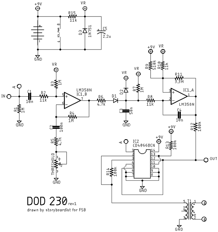
Sorry for the delay. Values seem correct to me. So, based upon the schematic, is this correct? 2 & 3 go to their respective xlr pins. Would pin 1 on the xlr go to the unlabeled interface point in the diagram? Thanks.
- Attachments
-
-
Manfred
- Tube Twister
Information
- Posts: 1945
- Joined: 04 Apr 2009, 23:42
- Has thanked: 1675 times
- Been thanked: 1360 times
Is the value of the threshold potentiometer known?Sorry for the delay. Values seem correct to me. So, based upon the schematic, is this correct? 2 & 3 go to their respective xlr pins. Would pin 1 on the xlr go to the unlabeled interface point in the diagram? Thanks.
Unfortunately, I don't have the pot. Was thinking it might be 500k but not certain.Manfred wrote: ↑24 Feb 2022, 00:13Is the value of the threshold potentiometer known?Sorry for the delay. Values seem correct to me. So, based upon the schematic, is this correct? 2 & 3 go to their respective xlr pins. Would pin 1 on the xlr go to the unlabeled interface point in the diagram? Thanks.
-
Fender3D

- Cap Cooler
sorry guys I don't get the purpose of injecting DC to output...
And again isn't output level too much high when you crank treshold pot? It's the same gain in MXR D+ or DOD 250 distortion, furthermore won't D1 and D2 clip signal?
And again isn't output level too much high when you crank treshold pot? It's the same gain in MXR D+ or DOD 250 distortion, furthermore won't D1 and D2 clip signal?
-
Scruffie
- Opamp Operator
That's the envelope section, seems the audio is dealt with passively and the output is pin 2 of the 4066.