Maestro - USS-1  [schematic]

Discussion regarding early stompbox technology: 1960-1975 Please keep discussion focused and contribute what info you have...
User avatar
Intripped
Cap Cooler
Information
Posts: 671
Joined: 25 Aug 2009, 01:03
Location: Italy
Has thanked: 991 times
Been thanked: 305 times

Post by Intripped »

this thing is definitely wicked... :blackeye i like it a lot!
...and even if it's far more complicated than everything i have ever built, i would like to give it a go.

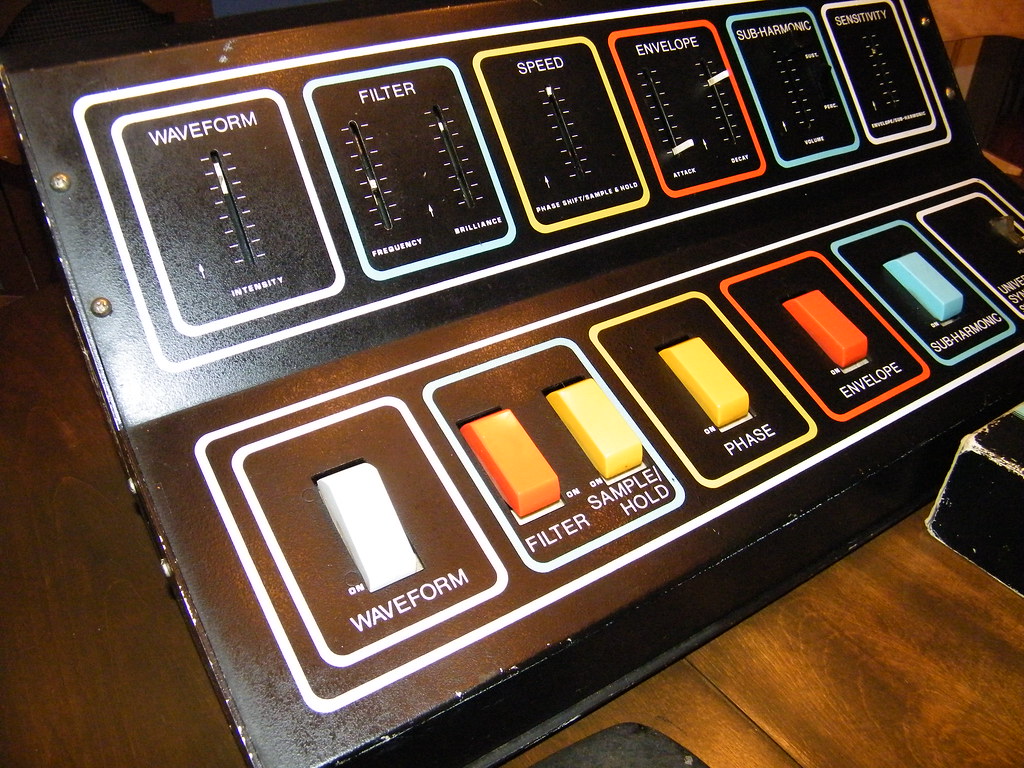
i'd like to divide the original BIG board in the different sub-units (filter/sample&hold - phaser - ...) and make it more diy-friendly.
i'm thinking of building each unit separately, probably with classic rotary-pots, and connect all the boards inside the box.
In order to accomplish this, i'm looking at the schem downloaded right now: i thought it was easy to separate the different sections of the circuit, but after this first glance it seems to be quite difficult... but i have to study it deeper.

anyway: are you guys going to exactly replicate the original layout or you would prefer to re-design the layouts for all the single sections of the circuit?
i would help in the process, i'm quite good with eagle-cad.

User avatar
cortezthekiller
Breadboard Brother
Information
Posts: 117
Joined: 10 May 2009, 21:33
my favorite amplifier: A large highway overpass
Location: Ottawa, Canada
Has thanked: 20 times
Been thanked: 52 times

Post by cortezthekiller »

So far I have traced about half of the circuit. There has been little differences between the factory schematic and the actual unit so far, though I have taken not of the few differences and will get an updated schematic up when it is fully traced. Just to take note, either the pinout of the 2N5172 is incorrect (which I don't think is the case) or they put all of them in wrong according to the schematic and somehow it still works? That is confusing me so I will examine those parts of the circuit an see what is going on.
On the first page of the schematic there is a connection that is going off of the page to the left at the top. This goes down to the 0.15 cap that connects to the base of Q1.
Another change is that all the power supply filter caps are 220uF (the schematic designates 125uF for most). The other difference is that the 100K resistor that goes to ground off of pin 6 of OPAMP A6 b is going to +V1 instead in the one I'm tracing. I should be able to finish tracing it and get all changes up for examination

Something to keep in mind if you wanted to do separate boards for each effect: many of the controls are interactive or have multiple functions. For instance the SPEED control is the phaser speed and the sample/hold speed. The FILTER control works as a stand-alone filter, or can be animated by the ENVELOPE controls and SENSITIVITY control, and the ENVELOPE controls are also for the attack/decay of the signal envelope when that section is activated. The SENSITIVITY control sets the control voltages for the FILTER and the SUB HARMONIC, and somehow also causes the SPEED of the SAMPLE/HOLD LFO to change if it maxed out.

So other than the WAVEFORM all the other effects involved require portions of other circuits which I think gives it an unpredictable and unique nature.

User avatar
Intripped
Cap Cooler
Information
Posts: 671
Joined: 25 Aug 2009, 01:03
Location: Italy
Has thanked: 991 times
Been thanked: 305 times

Post by Intripped »

mmmh, thanks, i didn't know about that
i would like to make a floor unit, so i would implement little mods (rotary pots - foot or toggle switches i will see)
anyway the idea was to etch the boards by my own: i see the etching of the original-dimensioned-BIIIIGG-board quite hard
i think also finding a new board for etching wouldn't be easy, but maybe i'm wrong.

so i think i will go with the separating idea anyway, but keeping all the interactions/condivisions between the effects.
what about the rocker-switches and the off board wiring? is it included in the schematic? (i'm studying it, but it's not clear yet)

...thanks for the work you're doing!

User avatar
cortezthekiller
Breadboard Brother
Information
Posts: 117
Joined: 10 May 2009, 21:33
my favorite amplifier: A large highway overpass
Location: Ottawa, Canada
Has thanked: 20 times
Been thanked: 52 times

Post by cortezthekiller »

So far I managed to trace the whole unit. There is not much difference between the factory schematic and the unit I'm working with.
What I thought was a pinout problem was an error I made. It turns out the 2n5172's in this unit are EBC as marked on their case, whereas the schematic and online datasheets denote an ECB pinout.

As for the switching, there are JFET's for each effect that are separate (a number in a large circle on the schematic) and when each of those points is connected to point 1 (also in a large circle in the upper right of the entire schematic), then the effect in question is turned on. I do not have the footswitch and am planning on building one. I noticed on the original footswitch there is a switch for each effect PLUS an extra switch for the effect on/off (master bypass?). Perhaps it is implemented by simply opening and closing the + voltage from reaching the other switches which are already engaged to be on or off? Though unsure what points 2 and 4 would be used for, which also connect to the 12-pin footswitch jack on the side. From what I've gathered, points 10 and 11 (tapped off of the AC secondary) are for the indicator lamps on the footswitch.

Hopefully will have the updated schematic up with supporting EXP. Pedal jack and panel mount/footswitch wiring scheme as well posted up.

User avatar
grizzlytone
Breadboard Brother
Information
Posts: 68
Joined: 14 Sep 2008, 13:34
Has thanked: 27 times
Been thanked: 83 times

Post by grizzlytone »

I'm gonna try to dump all the info I've collected on the USS-1 but it seems that files posted on this forum has to be < 1MB so I'll do it it multiple posts.

About the pdf PCB layout: Magenta traces are on the component side, Green solder points are ground (actual ground traces is easy to figure out...)

Hold on...
Attachments
Maestro USS-1 PCB layout.pdf
(418.2 KiB) Downloaded 187 times

User avatar
grizzlytone
Breadboard Brother
Information
Posts: 68
Joined: 14 Sep 2008, 13:34
Has thanked: 27 times
Been thanked: 83 times

Post by grizzlytone »

Interaction and trimmers...
Attachments
Maestro USS-1 Universal Synthesizer block schematic and trimpoints -small and crappy.bmp
Maestro USS-1 Universal Synthesizer block schematic and trimpoints -small and crappy.bmp (461.9 KiB) Viewed 3247 times

User avatar
grizzlytone
Breadboard Brother
Information
Posts: 68
Joined: 14 Sep 2008, 13:34
Has thanked: 27 times
Been thanked: 83 times

Post by grizzlytone »

Sheet #1...
Attachments
Maestro USS-1 Universal Synthesizer schematic sheet1 -small and crappy.bmp
Maestro USS-1 Universal Synthesizer schematic sheet1 -small and crappy.bmp (875.71 KiB) Viewed 3247 times

User avatar
grizzlytone
Breadboard Brother
Information
Posts: 68
Joined: 14 Sep 2008, 13:34
Has thanked: 27 times
Been thanked: 83 times

Post by grizzlytone »

Sheet #2.

That's it. Peace out brothers & sisters.
Attachments
Maestro USS-1 Universal Synthesizer schematic sheet2 -small and crappy.bmp
Maestro USS-1 Universal Synthesizer schematic sheet2 -small and crappy.bmp (932.73 KiB) Viewed 3247 times

User avatar
cortezthekiller
Breadboard Brother
Information
Posts: 117
Joined: 10 May 2009, 21:33
my favorite amplifier: A large highway overpass
Location: Ottawa, Canada
Has thanked: 20 times
Been thanked: 52 times

Post by cortezthekiller »

Thank you very much grizzlytone for the documentation you have provided.
That helps to figure out the proper switching scheme for the footswitch wiring.

Here is the updated factory schematic I have come up with. It is all one one page now:
Attachments
USS1 A FULL A.jpg

User avatar
grizzlytone
Breadboard Brother
Information
Posts: 68
Joined: 14 Sep 2008, 13:34
Has thanked: 27 times
Been thanked: 83 times

Post by grizzlytone »

cortezthekiller wrote:Thank you very much grizzlytone for the documentation you have provided.
That helps to figure out the proper switching scheme for the footswitch wiring.

Here is the updated factory schematic I have come up with. It is all one one page now:
Thanks Cortez. If you compare my schematic to the factory schematic you'll also notice that adjacent to Q6/Q7 in the factory schematic there's quite a few parts vital to the filter function missing in the factory schematic.

The S/H circuit in the USS-1 sounds even better than the S/H circuit in the Maestro stand-alone S/H unit. Good luck with the cloning /MB

User avatar
MARC-ERIC
Information
Posts: 12
Joined: 16 Dec 2011, 09:28
Has thanked: 1 time

Post by MARC-ERIC »

I bought one yesterday :D
I think mine is USS-1A version.

I will have to replace all the slide pot; many are broken and many are too scratchy...
Image

Can someone point me toward good quality replacement that will be perfect fit ?
Maybe someone has already done that...

User avatar
toneman
Resistor Ronker
Information
Posts: 343
Joined: 17 Jul 2007, 13:05
my favorite amplifier: anything that works
Completed builds: meatolation, wobolation, ringolation clones, PAiA synths/modulars, dipthonizer clone, MOTM modules, pedal mods and repairs
Location: sacatomatoes, Kali4neeaa
Has thanked: 183 times
Been thanked: 45 times

Post by toneman »

Mouser in the USA has lots of slide pots.
Check how many mm of travel they have, and the ohms and taper then look on the Mouser website.
U can download the slider pot page(s) in pdf.

here's a start for U----
http://www.mouser.com/catalog/catalogusd/646/849.pdf

afn
T
8)
Tone-to-the-Bone

User avatar
cortezthekiller
Breadboard Brother
Information
Posts: 117
Joined: 10 May 2009, 21:33
my favorite amplifier: A large highway overpass
Location: Ottawa, Canada
Has thanked: 20 times
Been thanked: 52 times

Post by cortezthekiller »

Also, keep in mind the actuator length when looking for sliders. The ones on the USS1 have fairly long actuators (in order to mount on the board and reach through the case to the slider cap). That detail was where I had difficulty finding the right one.

On mine, there was only one slider actuator broken, so I used a small cutting disc to form a groove in the plastic of the broken one and superglued a metal actuator arm from a recycled slider to get the length back to put on a slider cap. I have not had issues with it since, though I make sure I'm not adjusting them with my feet, or other things that would put unneeded stress on them.

PS: In the full schematic I put together from the factory ones I had not full labelled C10's polarity. To be sure, here is the updated version. Any additional corrections are welcome:
Attachments
USS1 A FULL A copy.jpg

User avatar
clintrubber
Breadboard Brother
Information
Posts: 100
Joined: 08 Oct 2008, 19:21
Location: The Netherlands
Has thanked: 16 times
Been thanked: 5 times
Contact:

Post by clintrubber »

Nice to see all this updated info! :D Much appreciated. I originally traded schematics years ago, with I forgot who, AnalogMan ? (FWIW, that zip-file on the first page may originate from my scanner), but wasn't aware of errors in the schematic.

Sliders ... yep, my Maestro could also use a few... the plastic is very brittle, easily snaps...

Bye & thanks again

User avatar
theyear2042
Breadboard Brother
Information
Posts: 68
Joined: 02 Oct 2007, 10:08
Been thanked: 2 times

Post by theyear2042 »

this is awesome

anyone keen on making a pcb? haha

User avatar
theyear2042
Breadboard Brother
Information
Posts: 68
Joined: 02 Oct 2007, 10:08
Been thanked: 2 times

Post by theyear2042 »

i'd been keen to pull the waveform (fuzz) and subharmonic circuits out to make an awesome dirt box

might have a look at this soon. anyone else have a similar idea?

Post Reply