Craig Anderton circuits
-
soulsonic

- Old Solderhand
Information
Good job with the heatsink/ground plane.... it's an essential thing.
-
RLBJR65

- Resistor Ronker
Information
Thanks.
If you soldered the IC directly to the board I think there is enough ground plane / heatsink that if no external heat sink would be required. They do have thermal overload protection so (fingers crossed) it would only get hot and shut off. Heck the board is less than 2" wide I could easily space things out a bit if more is required.
I don't know if the LM380N is still in production, National doesn't list it as obsolete anyway. I found plenty of them online, Futurelec has them for $1.00ea. I got some for 50 cents ea. at my favorite surplus dealer
Mouser has the NTE replacement NTE704A $6.23 ea. YIKES!
-
analogguru

- Old Solderhand
Information
Take care.... in the last years have also been around 8-pin-versions.I don't know if the LM380N is still in production, National doesn't list it as obsolete anyway. I found plenty of them online, Futurelec has them for $1.00ea. I got some for 50 cents ea. at my favorite surplus dealer
analogguru
There´s a sucker born every minute - and too many of them end up in the bootweak pedal biz.
-
RLBJR65
- Resistor Ronker
Information
Thanks AG!
Good catch! I'll make sure to note it on the layout.
It's such a simple circuit maybe I will make a board for the 8 pin too.
8 pin Layout https://img265.imageshack.us/img265/9606/caha8hv6.gif
Good catch! I'll make sure to note it on the layout.
It's such a simple circuit maybe I will make a board for the 8 pin too.
8 pin Layout https://img265.imageshack.us/img265/9606/caha8hv6.gif
-
RLBJR65
- Resistor Ronker
Information
-
RLBJR65
- Resistor Ronker
Information
Super Tone Control added https://img201.imageshack.us/img201/778 ... trozr1.gif
Question about the schem. in the feedback loop of IC 1D there are 3 - 10K then a tap labled M. What is it for? On the layout it just goes to a pad labeled M with no connection. No notes about it in the book.
Question about the schem. in the feedback loop of IC 1D there are 3 - 10K then a tap labled M. What is it for? On the layout it just goes to a pad labeled M with no connection. No notes about it in the book.
-
analogguru
- Old Solderhand
Information
In theory this is a "virtual ground" "summing bus". You could connect there another input signals with additional mixing resistors. For example a second filter.Question about the schem. in the feedback loop of IC 1D there are 3 - 10K then a tap labled M. What is it for?
You cannot connect a second op-amp stage (similar as shown) there.
The schematic shown is well known as "state-variable filter" and used nearly in every "Parametric Equalizer". also used in the EH Q-Tron/Mini-Q-tron, or the Tycobrahe Parapedal and may others
analogguru
There´s a sucker born every minute - and too many of them end up in the bootweak pedal biz.
-
bajaman

- Old Solderhand
Information
- Posts: 4549
- Joined: 26 Jun 2007, 21:18
- Location: New Brighton, Christchurch, NZ
- Has thanked: 596 times
- Been thanked: 2061 times
and, a modified version (state variable filter)
is used in the BBE Sonic Stomp pedal too
bajaman
is used in the BBE Sonic Stomp pedal too
bajaman
-
RLBJR65
- Resistor Ronker
Information
-
John Lyons

- Solder Soldier
RLBJR65
The point M on the board is not used. (been there...)
Once again, this one is a great tone control with radical as well as slight boosts or cuts.
Hooking up the STC to the envelope follower in the book would be nice as well for an auto wah type quack or sweeping filter.
Thanks for drawing these up!! I have the book(s) but the info needs to be out there...
John
-
RLBJR65
- Resistor Ronker
Information
Thanks John
I wonder if JD would complain about you making a few copies of those boards![[smilie=a_chuckle.gif]](./images/smilies/a_chuckle.gif "a_chuckle") Oh well I'm glad they pcb artwork is available and he did at least change the boards that used dual opamps.
Oh well I'm glad they pcb artwork is available and he did at least change the boards that used dual opamps.
I wonder if JD would complain about you making a few copies of those boards
-
RLBJR65
- Resistor Ronker
Information
-
RLBJR65
- Resistor Ronker
Information
First post in the threadluap77 wrote:I would very much like to build the Anderton "Stack in a Box". Does anybody have a schematic, pcb layout etc that they are willing to share?
-
RLBJR65
- Resistor Ronker
Information
-
RLBJR65
- Resistor Ronker
Information
-
RLBJR65
- Resistor Ronker
Information
RLBJR65 wrote:HeadPhone Amp from EPFM
https://img126.imageshack.us/my.php?ima ... amphs3.gif
I'll redraw the other projects as I get time.
You still got to get the book for build notes, tweaks and mods
Project #1 Preamp https://img61.imageshack.us/my.php?imag ... ampgj0.gif
Project #2 Metronome https://img61.imageshack.us/my.php?imag ... omeuv6.gif
Project #3 Passive Tone Controll (posted Meanderthal) https://i86.photobucket.com/albums/k99/ ... vetone.jpg
Project #4 Head Phone Amp (posted above)
Headphone amp layout. https://img267.imageshack.us/my.php?image=cahaik7.gif
Headphone Amp layout for 8 pin LM380N-8 https://img265.imageshack.us/img265/9606/caha8hv6.gif
Project #5 Mini Amp that uses an obsolete audio amp IC UA706 or TBA641B https://img412.imageshack.us/my.php?ima ... ampgm9.gif
Project #6 Ultra Fuzz https://img165.imageshack.us/my.php?ima ... uzzjd1.gif
Project #7 Bass Fuzz https://img106.imageshack.us/my.php?ima ... uzzqa0.gif
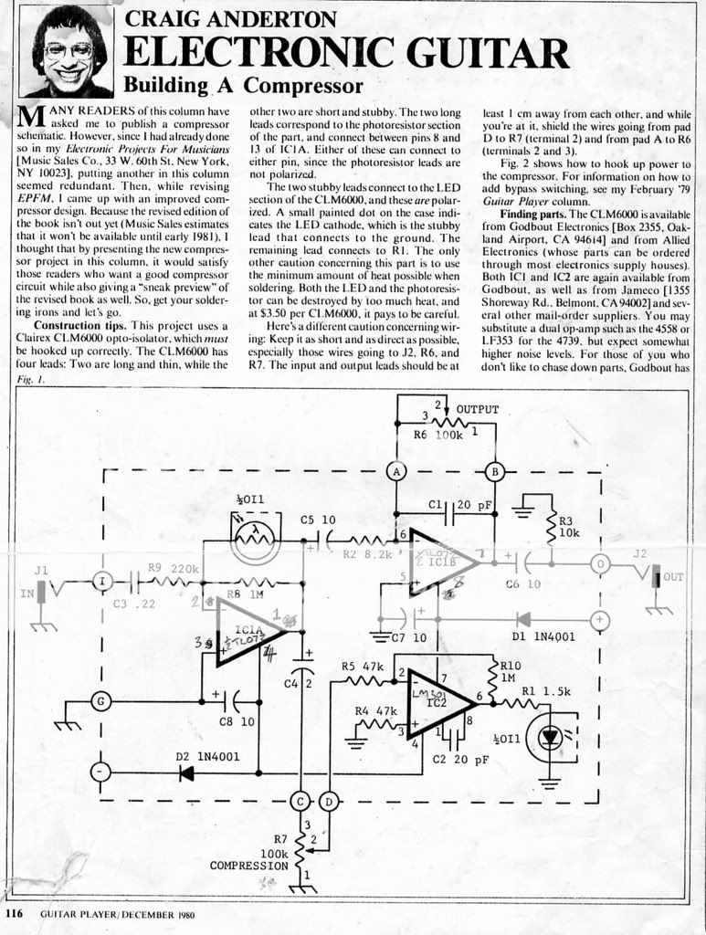
Project #8 Compressor / Limiter (posted ModMan) https://i197.photobucket.com/albums/aa2 ... or1980.jpg
Project #9 Ring Modulator https://img413.imageshack.us/my.php?ima ... torcd7.gif
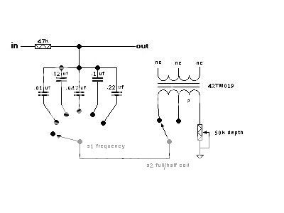
Project #10 Dual Filter Voicing Unit (Thanks Andrew!) Added PS info https://img106.imageshack.us/my.php?ima ... filig7.gif
Project #11 Adding Bypass switches. Won't do that one.
Project #12 Guitar rewiring. Telecaster Rewire http://users.adelphia.net/~cygnusx_1/anderton_jpeg.html
Project #13 Bipolar AC Adaptor: + / - 9v Power supply https://img530.imageshack.us/img530/325 ... terux0.gif
Project #14 Treble Booster https://img374.imageshack.us/img374/131 ... ostwr4.gif
Project #15 Electronic Foot Switch https://img517.imageshack.us/my.php?ima ... otsro9.gif
Project #16 Tuning Standard. Uses obsolete MK50240 Tone generator not worth re-drawing unless someone wants it.
Project #17 Super Tone Control https://img201.imageshack.us/img201/778 ... trozr1.gif
Project #18 8 in, out Mixer. https://img402.imageshack.us/img402/483 ... xerlr3.gif
Project #19 Using an Ohm-Milliammeter. NAH!
Project #20 Practice Play Along https://img237.imageshack.us/img237/309 ... ppaab6.gif
Project #21 Phase Shifter https://img461.imageshack.us/img461/743 ... terto8.gif
Project #22 Making patch cords. NAH!
Project #23 Talk Box. NAH!
Project #24 Tube Sound Fuzz (posted Modman) http://www.geocities.com/CollegePark/Li ... 55/tsf.gif
Project #25 Envelope Follower
Project #26 Spluffer, combination splitter buffer. https://img530.imageshack.us/img530/449 ... ferji7.gif
Project #27 Noise Gate
WOW, that will keep me busy for a while, I forgot there were that many!
I'll do them in order unless someone has a request.
-
RLBJR65
- Resistor Ronker
Information
Envelope Follower https://img166.imageshack.us/img166/935 ... oweql2.gif
Couple of usefull circuits from the back of the book. How to make a dual supply from a single 9v
https://img166.imageshack.us/img166/627 ... plycg1.gif
Couple of usefull circuits from the back of the book. How to make a dual supply from a single 9v
https://img166.imageshack.us/img166/627 ... plycg1.gif