B&M Sola Sound - Fuzz Unit [schematic]
-
Electric Warrior

- Diode Debunker
I got an X-Ray of that one lying about 
Clarendon Bold should be a pretty good match for the font, btw.. http://new.myfonts.com/fonts/adobe/clarendon/bold/
Clarendon Bold should be a pretty good match for the font, btw.. http://new.myfonts.com/fonts/adobe/clarendon/bold/
-
Electric Warrior
- Diode Debunker
and you gotta move the top left capacitor one row to the right. There's a 33k resistor where you put it.
-
peps1

- Solder Soldier
TURNS OUT I DIDNT SWITH ON PM NOTIFICATIONScruffie wrote:While Peps1 is involved in this subject... Check your DIY PMs! (Sorry for the De-Rail too)
will PM you tonight/tomorrow and sort them PCBs
-
peps1
- Solder Soldier
Cool....done that!Electric Warrior wrote:and you gotta move the top left capacitor one row to the right. There's a 33k resistor where you put it.
Here is what I got so far!
Points of query:
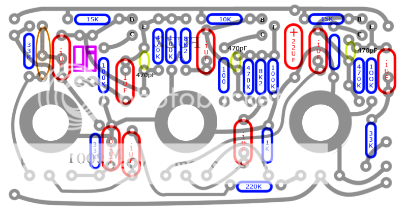
1:Used the value 003uf for the ceramic cap as thats what it is on the only Jumbo TB layout.....should be the same, right?
2: ceramic cap code 470 = 470pf?
And its 4Am here....but am I missing a resister here?

Good Night!
-
Scruffie

- Opamp Operator
Yes you are, but I can't see the value on any of the photos...And its 4Am here....but am I missing a resistor here?
Haha, no Worries man, will chat to you in the near future about them.TURNS OUT I DIDNT SWITH ON PM NOTIFICATION
will PM you tonight/tomorrow and sort them PCBs
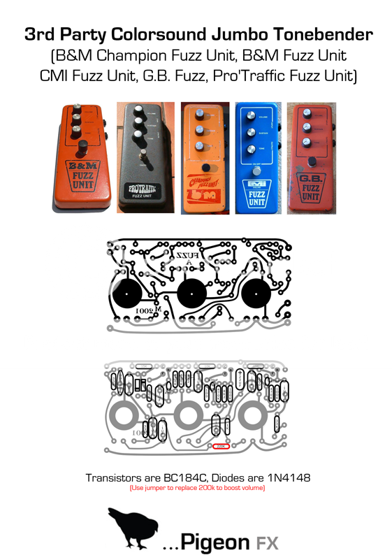
The missing resistor is 100 ohms. Also, you have the transistor pinouts labelled wrong. Should be C-B-E from top to bottom. The original transistors were BC184C.
A word of advice, that 220K resistor in series with the volume pot is completely useless and lowers the output quite a bit. Jumper it and you'll get more volume, otherwise you barely get unity with the volume pot maxed.
A word of advice, that 220K resistor in series with the volume pot is completely useless and lowers the output quite a bit. Jumper it and you'll get more volume, otherwise you barely get unity with the volume pot maxed.
-
Electric Warrior
- Diode Debunker
peps1 wrote:Cool....done that!Electric Warrior wrote:and you gotta move the top left capacitor one row to the right. There's a 33k resistor where you put it.
Here is what I got so far!
(...)
Points of query:
1:Used the value 003uf for the ceramic cap as thats what it is on the only Jumbo TB layout.....should be the same, right?
2: ceramic cap code 470 = 470pf?
sonicvi wrote:It's usually .0039uF and that's what the original schematic calls for. Sola Sound called the B&M circuit "Fuzz A" and it is identical to the Jumbo with the exception of a 220K resistor at the output. I'm not sure what the purpose of that resistor is as it reduces the volume quite a bit. The pots are usually either all log taper or log for the volume and sustain and linear for the tone. Everything else about this circuit is pretty much evident from the photos and the "Fuzz A/Jumbo Tone Bender" schematic on the web. I think everybody pretty much knows by now the Jumbo is the same circuit as the Big Muff with first pair of clipping diodes and post tone gain stage removed. Doesn't sound like much but they're pretty significant differences soundwise.Electric Warrior wrote:There's two or three different layouts for the jumbo circuit with vertical controls.
some have slightly different resistor values (39k instead of 33k and 10 instead of 8k2) and/or component types (ceramic caps vs. styroflex). What I believe to be the earlier units have tropical fish caps instead of the greenies.
The values of the ceramic/styro caps may vary as well, but it's hard to see in the pictures I found. I've seen styroflex caps with a 500pf color code. Others have the number 220 printed onto them (or is this the voltage rating?). The ceramics in the ebay pics are 470pF. Does anybody have some more data?
And I'm not quite sure about the small cap at lug 1 of the tone pot. is it supposed to be 0.003µF or 0.004µF?
-
Electric Warrior
- Diode Debunker
The Colorsound Supa Wah-Fuzz-Swell used the same circuit board as well
http://dam.10.forumer.com/viewtopic.php?t=1295
http://www.effectsdatabase.com/model/co ... swell/supa
http://dam.10.forumer.com/viewtopic.php?t=1295
http://www.effectsdatabase.com/model/co ... swell/supa
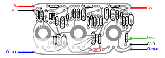
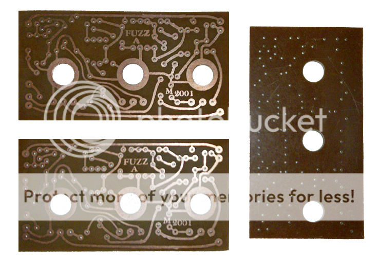
People should be able to work it out from the schematic, but maybe you could label the In, Out, Ground and +9V pads.
From top to bottom they are (using the component side):
Left side:
9V, Ground, Out
Right side:
9V, In, Ground, Out
From top to bottom they are (using the component side):
Left side:
9V, Ground, Out
Right side:
9V, In, Ground, Out
-
peps1
- Solder Soldier
Any more to add?Electric Warrior wrote:The Colorsound Supa Wah-Fuzz-Swell used the same circuit board as well
http://dam.10.forumer.com/viewtopic.php?t=1295
http://www.effectsdatabase.com/model/co ... swell/supa
Thanks sonicvi, have updated the PDFsonicvi wrote:People should be able to work it out from the schematic, but maybe you could label the In, Out, Ground and +9V pads.
From top to bottom they are (using the component side):
Left side:
9V, Ground, Out
Right side:
9V, In, Ground, Out
- Attachments
-
 Jumbo copy.pdf
- (986.59 KiB) Downloaded 248 times
 yumyumyum
 -
Electric Warrior
- Diode Debunker
Yes, on different boards, though:peps1 wrote:Any more to add?Electric Warrior wrote:The Colorsound Supa Wah-Fuzz-Swell used the same circuit board as well
http://dam.10.forumer.com/viewtopic.php?t=1295
http://www.effectsdatabase.com/model/co ... swell/supa
Vox Tone Bender Mark III (some of them) and Eurotec Black Box Fuzz Unit (2 knob)
-
analogguru
- Old Solderhand
Information
That´s wrong, because the layout is different in the Eurotec Fuzz.Electric Warrior wrote:Yes, on different boards, though:peps1 wrote:Any more to add?Electric Warrior wrote:The Colorsound Supa Wah-Fuzz-Swell used the same circuit board as well
http://dam.10.forumer.com/viewtopic.php?t=1295
http://www.effectsdatabase.com/model/co ... swell/supa
Vox Tone Bender Mark III (some of them) and Eurotec Black Box Fuzz Unit (2 knob)
analogguru
There´s a sucker born every minute - and too many of them end up in the bootweak pedal biz.
-
Electric Warrior
- Diode Debunker
but the circuit is the same, isn't it?
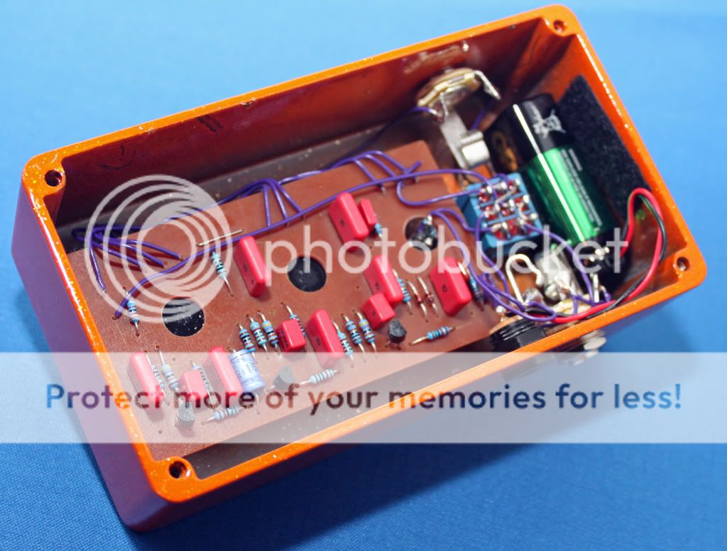
built one of these (actually two the same) using peps boards for myself,
Here is some pics. Sounds great and well worth the effort. The mojo of the original looking boards just adds to the sound
Cheers Peps!!

Here is some pics. Sounds great and well worth the effort. The mojo of the original looking boards just adds to the sound
Cheers Peps!!
Owner and chief Solder wielder at ThorpyFx