BK Butler - Tube Driver  [schematic]

Discussion regarding early stompbox technology: 1960-1975 Please keep discussion focused and contribute what info you have...
User avatar
DrNomis
Old Solderhand
Information
Posts: 6804
Joined: 16 Jul 2009, 04:56
my favorite amplifier: Self-Built Valve Amp Head :)
Completed builds: Dallas Arbiter Fuzz Face,Tone Bender Professional Mk 3,Tone Bender 3-Knob,Baja BK Butler Tube Driver,Baja Real Tube Overdrive,Roger Mayer Octavia,EH Soul Preacher,Tech 21 XXL Distortion,MFOS Weird Sound Generator.
Location: Darwin,Northern Territory Australia
Has thanked: 98 times
Been thanked: 275 times

Post by DrNomis »

theehman wrote:I thought you were talking about one of these:
img58.jpg
They use 6AV6/6AT6 tubes


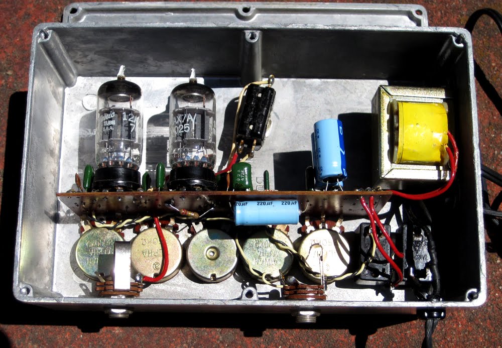
I'm interested in building one of these 1979 Tube Drivers, and I'm wondering if anyone knows where I could find a schematic for this model... :hmmm: :scratch:
Genius is not all about 99% perspiration, and 1% inspiration - sometimes the solution is staring you right in the face.-Frequencycentral.

User avatar
MWichni
Degoop Doctor
Information
Posts: 378
Joined: 18 Apr 2008, 19:08
my favorite amplifier: HI-WATT DR103
Completed builds: Neo-Vibe, EH Big Muff Ram's Head, MXR Dynacomp, Demeter Compulator, Bk Butler Tube Driver, MXR Distortion +, Maxon OD880, MXR Phase 45, ProCo Rat, Colorsound Power Boost, BOSS CE-2, Rebote Delay 2.5, EH Electric Mistress, Fuzz Face, Tycobrahe Octavia, EH Pulsar. Custom made cabinet with 2x12" Celestion Vintage 30's.
Location: Poland: Szczecin
Has thanked: 7 times
Been thanked: 57 times

Post by MWichni »

Hi guys, I will upload a schematic and pcb layout from a traced Chandler Tube Driver soon.

User avatar
Kap'n
Information
Posts: 6
Joined: 16 Feb 2010, 01:14
Has thanked: 1 time
Been thanked: 2 times

Post by Kap'n »

How do these differ from the Paul C "Mini Boogee" pedal?

User avatar
ppluis0
Diode Debunker
Information
Posts: 915
Joined: 14 Jul 2010, 18:33
Location: Argentina
Has thanked: 127 times
Been thanked: 299 times

Post by ppluis0 »

The Mini Boogee has two 12AX7 inside, as can be seen in the following images found in the web:

Image

Image

Looks like this unit works with bipolar low voltage supply as the Tube Driver that were constructed after this line of pedals.

Will be interesting to trace one of this units due I cant´t see any transistor or op amps (at least in the first photograph), and all the amplification looks to be done with tubes.

Any forum member has acces to one of these oldies ??

Cheers,
Jose

User avatar
MWichni
Degoop Doctor
Information
Posts: 378
Joined: 18 Apr 2008, 19:08
my favorite amplifier: HI-WATT DR103
Completed builds: Neo-Vibe, EH Big Muff Ram's Head, MXR Dynacomp, Demeter Compulator, Bk Butler Tube Driver, MXR Distortion +, Maxon OD880, MXR Phase 45, ProCo Rat, Colorsound Power Boost, BOSS CE-2, Rebote Delay 2.5, EH Electric Mistress, Fuzz Face, Tycobrahe Octavia, EH Pulsar. Custom made cabinet with 2x12" Celestion Vintage 30's.
Location: Poland: Szczecin
Has thanked: 7 times
Been thanked: 57 times

Post by MWichni »


User avatar
ppluis0
Diode Debunker
Information
Posts: 915
Joined: 14 Jul 2010, 18:33
Location: Argentina
Has thanked: 127 times
Been thanked: 299 times

Post by ppluis0 »

Hi Mwichni,

Thank you for the schematic you posted...!!!!!!!

Can you post the link of the thread where this diagram was found, in order to read the opinions about this pedal ??

Thanks in advance, and best regards,
Jose

User avatar
pete_el34
Information
Posts: 7
Joined: 12 Dec 2011, 14:10
Location: Portugal & Germany
Has thanked: 12 times
Been thanked: 1 time

Post by pete_el34 »

Hi all!

As promised here is the schematic of the early tube driver traced from the guts posted on this thread.
The most significant differences compared to the new RI edition are:

---> R14: On the new RI version it increased from 2,2k to 22k. Several people reported that the tone stack reacted different on the new version vs. the old one. This value change is the reason.
Maybe 2,2k works better when one rolls off both the Bass and High a la Eric Johnson??
---> R7,R8: From the pictures the plate resistors look like 6,8k. I was expecting 47k here. Was this unit moded for lower gain tubes? "Tube Driver" can you please measure the bias voltage in both R7 and R8?
---> R12: increased from 10k to 22k in the new RI Edition. This gives more gain/less headroom.
---> C3: Was not identified on the guts pictures. I'm guessing its value is 120pf. "Tuberiver" can you confirm this?

The new RI version is better than the old one regarding PWR Supply, noise etc.. But i would maybe change R14 and R12 to the old values and listen what happens.

If anyone there has one of this early tube drivers please post the guts. I want to check the values of R7, R8, R12, R14, C3 on other units.
With the files that i attach here is very easy to find the components on the PCB.

Enjoy! ;)
BK Butler Early Garage Made Tube Driver Schematic
BK Tubedriver 003 PCB Top Layer
BK Tubedriver 003 PCB Top Layer.png (442.8 KiB) Viewed 10097 times
BK Tubedriver 016 PCB traces only
BK Tubedriver 016 PCB traces only.png (412.69 KiB) Viewed 10097 times
BK Tubedriver 016 PCB traces and caps
BK Tubedriver 016 PCB traces and caps.png (411.43 KiB) Viewed 10097 times
BK Tubedriver 016 PCB full render
BK Tubedriver 016 PCB full render.png (416 KiB) Viewed 10097 times

User avatar
pete_el34
Information
Posts: 7
Joined: 12 Dec 2011, 14:10
Location: Portugal & Germany
Has thanked: 12 times
Been thanked: 1 time

Post by pete_el34 »

Forgot to mention before, if you have a Chandler Wall Mart Tube driver you can easily convert it to a "authentic" tube driver by rebuilding the tone stack section.
When chandler copied the BK Butler design they totally messed up the Tone Stack Section.. All schematics to compare the different versions are here on this thread ;)

User avatar
pete_el34
Information
Posts: 7
Joined: 12 Dec 2011, 14:10
Location: Portugal & Germany
Has thanked: 12 times
Been thanked: 1 time

Post by pete_el34 »

On the post above of course i was refering to the 4 Knob Chandler Tube Driver with Wall Mart.

User avatar
pete_el34
Information
Posts: 7
Joined: 12 Dec 2011, 14:10
Location: Portugal & Germany
Has thanked: 12 times
Been thanked: 1 time

Post by pete_el34 »

MWichni wrote:Hi guys, I will upload a schematic and pcb layout from a traced Chandler Tube Driver soon.
Hi! Do you have the guts of that Chandler Tube Driver? Can you post them?

Thanks!

User avatar
MWichni
Degoop Doctor
Information
Posts: 378
Joined: 18 Apr 2008, 19:08
my favorite amplifier: HI-WATT DR103
Completed builds: Neo-Vibe, EH Big Muff Ram's Head, MXR Dynacomp, Demeter Compulator, Bk Butler Tube Driver, MXR Distortion +, Maxon OD880, MXR Phase 45, ProCo Rat, Colorsound Power Boost, BOSS CE-2, Rebote Delay 2.5, EH Electric Mistress, Fuzz Face, Tycobrahe Octavia, EH Pulsar. Custom made cabinet with 2x12" Celestion Vintage 30's.
Location: Poland: Szczecin
Has thanked: 7 times
Been thanked: 57 times

Post by MWichni »

I try to post something during this weekend. Sorry for the delay but I don't have much time at the moment. Thanks for your kind words.

User avatar
DougH
Transistor Tuner
Information
Posts: 1087
Joined: 18 Aug 2007, 04:53
Has thanked: 4 times
Been thanked: 23 times

Post by DougH »

Aron has a schem for the early BK circuit I believe. That's what I based my Pentode Driver on.

User avatar
MWichni
Degoop Doctor
Information
Posts: 378
Joined: 18 Apr 2008, 19:08
my favorite amplifier: HI-WATT DR103
Completed builds: Neo-Vibe, EH Big Muff Ram's Head, MXR Dynacomp, Demeter Compulator, Bk Butler Tube Driver, MXR Distortion +, Maxon OD880, MXR Phase 45, ProCo Rat, Colorsound Power Boost, BOSS CE-2, Rebote Delay 2.5, EH Electric Mistress, Fuzz Face, Tycobrahe Octavia, EH Pulsar. Custom made cabinet with 2x12" Celestion Vintage 30's.
Location: Poland: Szczecin
Has thanked: 7 times
Been thanked: 57 times

Post by MWichni »

If someone can please verify it. I built one but I don't remember which pcb file was the final one.
Attachments
tdpcbfinalu.png
td2e.gif

User avatar
andregarcia57
Cap Cooler
Information
Posts: 572
Joined: 16 Nov 2008, 15:42
Has thanked: 72 times
Been thanked: 108 times

Post by andregarcia57 »

MWichni wrote:If someone can please verify it. I built one but I don't remember which pcb file was the final one.
is checked?

User avatar
MWichni
Degoop Doctor
Information
Posts: 378
Joined: 18 Apr 2008, 19:08
my favorite amplifier: HI-WATT DR103
Completed builds: Neo-Vibe, EH Big Muff Ram's Head, MXR Dynacomp, Demeter Compulator, Bk Butler Tube Driver, MXR Distortion +, Maxon OD880, MXR Phase 45, ProCo Rat, Colorsound Power Boost, BOSS CE-2, Rebote Delay 2.5, EH Electric Mistress, Fuzz Face, Tycobrahe Octavia, EH Pulsar. Custom made cabinet with 2x12" Celestion Vintage 30's.
Location: Poland: Szczecin
Has thanked: 7 times
Been thanked: 57 times

Post by MWichni »

I'll check if it was this pcb file that I used for etching my tube driver.

User avatar
imaradiostar
Information
Posts: 39
Joined: 17 Oct 2008, 09:46
Has thanked: 3 times
Been thanked: 8 times

Post by imaradiostar »

I once owned one of these and sold it on ebay because my rackmounted tube driver sounded better. It wasn't a bad pedal but it required very careful tube selection to sound decent. I noticed an error (really two) compared to what I had in mine- the 220k from the wiper of the treble pot to the bottom of the treble pot and the wiper of the bass pot should be wired to one end of the bass pot- I don't recall which.

jamie

User avatar
imaradiostar
Information
Posts: 39
Joined: 17 Oct 2008, 09:46
Has thanked: 3 times
Been thanked: 8 times

Post by imaradiostar »

I meant to say the 200k is wired between the wiper lug and the bottom lug of the treble pot, changing the value of the pot as you sweep the control.

jamie

User avatar
imaradiostar
Information
Posts: 39
Joined: 17 Oct 2008, 09:46
Has thanked: 3 times
Been thanked: 8 times

Post by imaradiostar »

ugh, how do I edit my bad posts? I keep saying it wrong!

-the 220k resistor is connected from the wiper of the treble pot to the bass end of the treble pot

-the bass pot is wired as a variable resistor with one end tied to the middle lug so that when the control as at max, the pot is at its full value.

jeez.

jamie

User avatar
eruarou
Information
Posts: 26
Joined: 13 Feb 2012, 20:18
Has thanked: 4 times

Post by eruarou »

MWichni wrote:If someone can please verify it. I built one but I don't remember which pcb file was the final one.
anyone know if this thing is right? :D

User avatar
Stratocaster-Sam
Information
Posts: 12
Joined: 26 Feb 2012, 21:16

Post by Stratocaster-Sam »

eruarou wrote:
MWichni wrote:If someone can please verify it. I built one but I don't remember which pcb file was the final one.
anyone know if this thing is right? :D
Anyone?...

Post Reply