Page 1 of 1
pcb tracing
Posted: 13 Jul 2017, 22:42
by POTL
Hello everyone, a question of a beginner
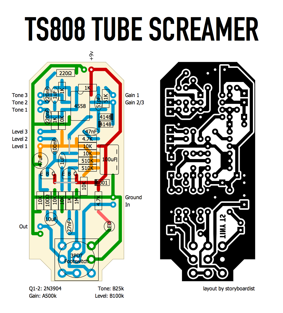
So it is necessary to bring to each component a separate power line (in the figure below from the main line, each component has its own line)

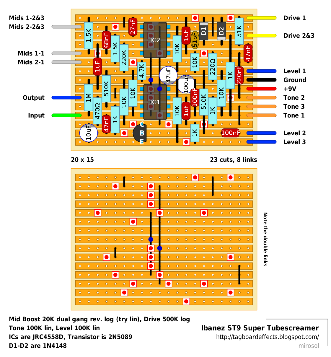
In the second figure there is one line on which all components are connected, that is, the current passes through 1 of the component's legs and then goes to the next

Are there any differences in sound and noise or there is no difference?
Re: pcb tracing
Posted: 14 Jul 2017, 09:06
by plush
Hi!
There is always a difference, the main thing that is important - if it is audible or not.
PCB tracing is all about placing you elements in optimal way, making the circuit compact and also eliminating possible interferences and parasitic capacitances.
As far as i know, breadboards have more capacitance in them, because all these copper lines act like a capacitor, adding some picofarads with each connected row and altering your tone a little bit. This is more important in high frequency circuits, than low freq audio. So, do not bother yourself.
Quality-traced pcb always sounds better for your oscilloscope and your personal ocd. Trust your ears and always progress.
p.s. if i were you, i'd check eevblog's youtube channel for more info about this stuff
Re: pcb tracing
Posted: 14 Jul 2017, 09:28
by deltafred
For such as stomp boxes as long as all the components are connected to the power lines they need it doesn't matter how it is done.
On the Vero layout it is usual to try and use one track for each power line to save tracks. When doing a PCB layout a lot of people will try and get a nice neat component layout then connect the power lines as needed.
For high current circuits e.g. power amps and high current power supplies, the current carrying capacity of the track has to be taken into consideration, wider tracks for higher current. For such circuits it is advisable (for circuit stability) to run supplies for control circuitry separate from high current tracks.
See also - "star grounding" often used on ground tracks/wires to make high current circuits more stable and less noisy. On multi-layer PCBs there is often a ground plane to help with screening and also to stop crosstalk between high voltage signals and sensitive input tracks. If you really want to get technical there is something called a "guard ring" for high gain, high impedance input circuits, Google this if interested.
Re: pcb tracing
Posted: 14 Jul 2017, 14:26
by POTL
deltafred wrote:For such as stomp boxes as long as all the components are connected to the power lines they need it doesn't matter how it is done.
On the Vero layout it is usual to try and use one track for each power line to save tracks. When doing a PCB layout a lot of people will try and get a nice neat component layout then connect the power lines as needed.
For high current circuits e.g. power amps and high current power supplies, the current carrying capacity of the track has to be taken into consideration, wider tracks for higher current. For such circuits it is advisable (for circuit stability) to run supplies for control circuitry separate from high current tracks.
See also - "star grounding" often used on ground tracks/wires to make high current circuits more stable and less noisy. On multi-layer PCBs there is often a ground plane to help with screening and also to stop crosstalk between high voltage signals and sensitive input tracks. If you really want to get technical there is something called a "guard ring" for high gain, high impedance input circuits, Google this if interested.
Thank you!


