sparing a cap i guess?RnFR wrote:what's the advantage of grounding the gain pot to Vr?
Dinosaural/Lovetone Tube Bender [traced]
-
The Rotagilla

- Diode Debunker
So we're missing the Tone Shift option then on Güero 2.0's layout, yes? Nightraven, any chance you could fill in the missing pieces? Thanks!
The television will not be revolutionized.
-
nightraven

- Breadboard Brother
i could try!
here are some photos of the switch. one lug goes to that orange capacitor but the capacitor is unmarked on both sides, and then continues on to connect with C5 (labelled 2A103J) on the PCB (i'm assuming that's the same as C5 on the layout). the other lug of the switch looks like it is going to ground on the output jack (right?).


(the little black wire that slips just on top of TR6 to the green capacitor, C5)
excuse the limited knowledge - hope it was enough to help
let me know if any additional photos are needed
here are some photos of the switch. one lug goes to that orange capacitor but the capacitor is unmarked on both sides, and then continues on to connect with C5 (labelled 2A103J) on the PCB (i'm assuming that's the same as C5 on the layout). the other lug of the switch looks like it is going to ground on the output jack (right?).
(the little black wire that slips just on top of TR6 to the green capacitor, C5)
excuse the limited knowledge - hope it was enough to help
let me know if any additional photos are needed
https://fuzzboxes.org | authoritative and clickbait-free resource for 1960s fuzz pedals
-
batteryacidtea
- Breadboard Brother
The other lug of the "flying capacitor" goes to the ground, not output. Thanks for the pics, btw!
-
Nocentelli

- Tube Twister
Information
- Posts: 2222
- Joined: 09 Apr 2009, 07:06
- Location: Leeds, UK
- Has thanked: 1154 times
- Been thanked: 954 times
Please note that this layout is for the kit/project magazine version, according to guero's pdf schematic, i.e. no tone shift.
I've breadboarded it with 2N3904/2N3906 and it sounds really good, but i'm going to wait until I get the OG transistors before i build this layout, so please cast a critical eye and compare to schematic if you plan to build:
I'd love to update the layout with the toneshift included, so can anyone see what's happening in the pics, or suggest what the tone shift is? I thought it might be simply adding parallel caps to alter C5 and C6 (i.e. lowpass and highpass caps in the tonestack), but I've tried both doubling and halving their values, and neither seems great: Halving makes it VERY trebly, and doubling them makes the tone knob rather ineffectual. I've only got 50k lin pots, so this incorrect taper might be masking some of the usefulness of the variations I've tried.
I'd love to update the layout with the toneshift included, so can anyone see what's happening in the pics, or suggest what the tone shift is? I thought it might be simply adding parallel caps to alter C5 and C6 (i.e. lowpass and highpass caps in the tonestack), but I've tried both doubling and halving their values, and neither seems great: Halving makes it VERY trebly, and doubling them makes the tone knob rather ineffectual. I've only got 50k lin pots, so this incorrect taper might be masking some of the usefulness of the variations I've tried.
modman wrote: ↑ Let's hope it's not a hit, because soldering up the same pedal everyday, is a sad life. It's that same ole devilish double bind again...
-
mictester

- Old Solderhand
Information
The drive pot is also used to set the DC bias point of the third transistor.MicMicMan wrote:sparing a cap i guess?RnFR wrote:what's the advantage of grounding the gain pot to Vr?
There are two errors in the version that was published:
The first transistor base-to-ground resistor is the wrong value (I'll leave the correction to those who can work these things out - I've given up providing that kind of info here).
The types of transistors are wrong. Sure, you could build it with 2SC1815s and a 2SA1015, or 2N3706s and a 2N3703, but it wouldn't sound like the original.
I don't know who Dinosaural are, but they obviously recognise a good circuit to "borrow".
"Why is it humming?" "Because it doesn't know the words!"
-
Nocentelli
- Tube Twister
Information
- Posts: 2222
- Joined: 09 Apr 2009, 07:06
- Location: Leeds, UK
- Has thanked: 1154 times
- Been thanked: 954 times
mictester wrote:I don't know who Dinosaural are, but they obviously recognise a good circuit to "borrow".
Who are you, and what have you done? and if you designed this circuit, can you tell us the proper Q1 base resistor and correct transistors to use, please?Dan Coggins - http://www.dinosaural.com/aboutus.asp wrote:About Dinosaural
In early 1995 I left my BBC engineering post and co-founded Lovetone® with Vlad Naslas. Our first product was the Meatball™, which was initially conceived as "a big envelope follower with 10 knobs". I designed the circuitry for all eight Lovetone products, including the Meatball. Vlad did the enclosures and graphics as well as the marketing in the early years, and we both came up with the overall concepts and "vision".
My Dinosaural® "Tube Bender™" (an all-transistor overdrive pedal design with authentic valve sound - not currently available) was something I designed partly in collaboration with David Petersen as part of a series of kits (mostly otherwise Dave's own designs, but I helped with the PCB's) for the UK "Guitar and Bass" magazine. The Tube Bender™was manufactured, marketed and sold via Dinosaural between 2003 and 2007. Famous users included Manfred Mann who used one on his electric piano and Snow Patrol who bought a number of them! Back in 1997. Dave and I had an interesting project researching Brian May's "Deacy" amp circuit (via Greg Fryer) from two photgraphs and producing a convincing sounding prototype replica for the Queen guitarist! I did amp repairs, as well as repairs and modifications to lots of classic FX pedals and Echo machines, and quite a few of those via CCGX (Charlie Chandlers' esteemed shop in Hampton Wick). Also, via CCGX I designed and built some custom equipment for luminaries such as Pete Townshend of the Who and Robbie McIntosh of the Pretenders, etc. I also did a few repair jobs for Radiohead, including restoring Thom Yorke's Selmer Stadium amp that I believe he used extensively on his solo album a few years back.
Lovetone® created and sold many high quality and innovative analogue guitar effects boxes to musicians in all corners of the world. I founded Dinosaural® in 2002 to provide exclusive warranty repair and technical support for all Lovetone products as well as other brands of classic analogue electronic music equipment.
I finally left the Lovetone® business after 13 years in March 2008, and from January 2009 stopped working on Lovetone products altogether owing to changes in circumstances.
I am now pursuing a full-time career as an employee working with both analogue and digital electronics. Since winding down Dinosaural to a relative "tick-over" in early 2007, I have worked on the design and test of Magnetometers and high-voltage pulse circuits, including PCB design. And I'm loving playing the guitar again after years of using it mainly as a "test generator"!
I'd like to thank all of my customers over the years for being great to deal with. I am sorry to disappoint those who want(ed) their Lovetone boxes fixed, but I had to "draw a line in the sand" in the end. I intend to resurface in "guitar effects land" once again eventually....so watch this space!
Dan Coggins
Wantage
Updated: April 6th 2012
modman wrote: ↑ Let's hope it's not a hit, because soldering up the same pedal everyday, is a sad life. It's that same ole devilish double bind again...
-
mictester
- Old Solderhand
Information
Looks like I'm going to have to change my name to "Dave" for credibility....Nocentelli wrote: Who are you, and what have you done? and if you designed this circuit, can you tell us the proper Q1 base resistor and correct transistors to use, please?
What have I done? Lots. I've been around a long time.
If you know so much about the circuit, you'd be able to tell us the correct values. A further look revealed another minor error too.
The original transistors were metal canned "Mullard" types - if you know what you're doing you can work out the best ones to use.
There are also three missing components from the circuit as published earlier in this thread, but they're not too important to the way the thing sounds.
Incidentally, the first builds of these were in Europe but many went to the 'States - one was used on a Steely Dan album in the mid-70s!
"Why is it humming?" "Because it doesn't know the words!"
-
Nocentelli
- Tube Twister
Information
- Posts: 2222
- Joined: 09 Apr 2009, 07:06
- Location: Leeds, UK
- Has thanked: 1154 times
- Been thanked: 954 times
Look, you said you didn't know who Dinosaural was, so I posted the information for your benefit. I don't know anything about the circuit (nor did I claim to) or its origins, which is why I asked about the tone shift. I have no abilities to calculate the base resistor required, which is why I asked for your assistance.
I know all the stuff you've posted here quite well, I've built several of your circuits, and the 1969 fuzz is still on my pedalboard, because I think it's great. I've avoided getting involved in any mictester bashing here at FSB because I've always reasoned it's entirely down to you if you want to remain anonymous whilst claiming to have designed all sorts of different circuits that pop up here. I posted a link to your tonebender at DIYSB a while back, only for the forum to descend on me, adamant it was a straight rip-off of the Hot Silicon - Again, I just deleted my post rather than engage in a discussion, I don't really care about who came up with the circuit. This wears a bit thin, however, when you appear in a thread and effectively say "the schematic is wrong, but I won't tell you the correct values" and appear to be claiming it as one of yours. Maybe you feel I/we should just learn how to correct the schematic for ourselves: However, there is a forum rule about teasing - If you don't want to share, please just keep it to yourself.
I know all the stuff you've posted here quite well, I've built several of your circuits, and the 1969 fuzz is still on my pedalboard, because I think it's great. I've avoided getting involved in any mictester bashing here at FSB because I've always reasoned it's entirely down to you if you want to remain anonymous whilst claiming to have designed all sorts of different circuits that pop up here. I posted a link to your tonebender at DIYSB a while back, only for the forum to descend on me, adamant it was a straight rip-off of the Hot Silicon - Again, I just deleted my post rather than engage in a discussion, I don't really care about who came up with the circuit. This wears a bit thin, however, when you appear in a thread and effectively say "the schematic is wrong, but I won't tell you the correct values" and appear to be claiming it as one of yours. Maybe you feel I/we should just learn how to correct the schematic for ourselves: However, there is a forum rule about teasing - If you don't want to share, please just keep it to yourself.
modman wrote: ↑ Let's hope it's not a hit, because soldering up the same pedal everyday, is a sad life. It's that same ole devilish double bind again...
-
LaceSensor
- Cap Cooler
With the greatest respect, I agree it would be nice if you could simply help, please, mictester.
As it is now it just seems like you are being obtuse and preventing a nice project from getting completed, which is very frustrating. Not all of us have the depth of knowledge experience and time and probably just the required acumen and in such cases if the answer is known why not just post it up rather than make people's lives difficult...
And we aren't really talking bout whatever original circuit this is, rather the version that was commercialised as the dinosaural tube bender, so whatever metal can mallards can or were used is kinda irrelevant seeing as the dinosaural used bc549 and bc307 transistors... So colour me confused why metal can mullards even matter??
-
RnFR
- Old Solderhand
Information
let's do the time warp again...
I'm getting a strange feeling of deja vu reading this thread.
I'm getting a strange feeling of deja vu reading this thread.
"You've converted me to Cubic thinking. Where do I sign up for the newsletter? I need to learn more about how I can break free from ONEism Death Math." - Soulsonic
Blog-APOCALYPSE AUDIO
Blog-APOCALYPSE AUDIO
-
mictester
- Old Solderhand
Information
The quietest transistors were the BC109C for the NPNs and the BC179C for the PNP. The lack of hiss was why it recorded so well. (We tried LOTS of different transistors back when this was new - these were by far the best). The base to ground resistor in the first stage should be 120K (some builds used 100k in series with a 22k). There is a missing 100p ceramic capacitor from base to emitter of the first transistor - used to get rid of radio breakthrough. There should also be a larger electrolytic across the supply rails - the originals had orange axial 330µF ones, but 220µ or 470µ will be perfectly good. Some examples had 3n9 or even 3n3 in place of the 4n7 in the tone control - it gave greater range, but got really thin sounding at one end. There should be an "idiot diode" across the rails as well. Finally - in some environments, the output impedance was inconveniently high, so there was an emitter follower (using an extra BC109C) to buffer the output of the volume control.LaceSensor wrote:With the greatest respect, I agree it would be nice if you could simply help, please, mictester.
As it is now it just seems like you are being obtuse and preventing a nice project from getting completed, which is very frustrating. Not all of us have the depth of knowledge experience and time and probably just the required acumen and in such cases if the answer is known why not just post it up rather than make people's lives difficult...
And we aren't really talking bout whatever original circuit this is, rather the version that was commercialised as the dinosaural tube bender, so whatever metal can mallards can or were used is kinda irrelevant seeing as the dinosaural used bc549 and bc307 transistors... So colour me confused why metal can mullards even matter??
This is a fairly low gain pedal so it's quite easy to keep it quiet. You do have to take note of "star point" earthing, however to minimise hum and noise. I breadboarded one earlier with modern "low noise" transistors (5088 and 5089), and it hissed quite a lot more than a vintage original with the metal-canned Mullards.
It's a pleasant change from the run-of-the-mill diode clippers, and actually makes use of the slightly warped transfer characteristic of a long-tailed-pair. It goes from a virtually clean, slightly boosted signal to a downright dirty distorted sound, but it doesn't give the extended sustain you expect with most distortion circuits. Players like it because their instrument retains a range of pick sensitivity (that's lost with most designs).
Other modifications that are interesting: remove the first two transistors and replace with your favourite op-amp lowpass filter with a bit of gain. Follow the long-tailed pair with another tone shaping op-amp circuit (perhaps the other half of a dual) and you can have some very interesting sounds that you won't hear elsewhere.
A similar approach turns up in "Arsenio Novo"'s "Night Train" pedal. This an interesting starting point for a whole range of other effects. It's fascinating to play with the differential input of an op-amp with its inputs seeing the collectors of a long-tailed pair....
"Why is it humming?" "Because it doesn't know the words!"
-
LaceSensor
- Cap Cooler
Cheers buddy very useful as always.
-
hbo
- Breadboard Brother
Information
Thanks for the schematic Steven_M and the mod/fix suggestions mictester. I put together a vero for this one for no particular reason.
-
Nocentelli
- Tube Twister
Information
- Posts: 2222
- Joined: 09 Apr 2009, 07:06
- Location: Leeds, UK
- Has thanked: 1154 times
- Been thanked: 954 times
Another verified vero, with mic's suggested mods to the guero schematic:
If I was going to build another, I might be tempted to add a final gain stage to boost the output a little: The minimum drive setting gives an output level not that much above unity, and it would be nice to be able to use it as a slightly gritty booster.
modman wrote: ↑ Let's hope it's not a hit, because soldering up the same pedal everyday, is a sad life. It's that same ole devilish double bind again...
-
aion

- Solder Soldier
Information
I've been really hoping to get one of the original Tube Benders so I could trace it and see if it was different from the magazine version. There are only 150 of them out there so it seemed pretty unlikely, but it was on the wish list anyway.
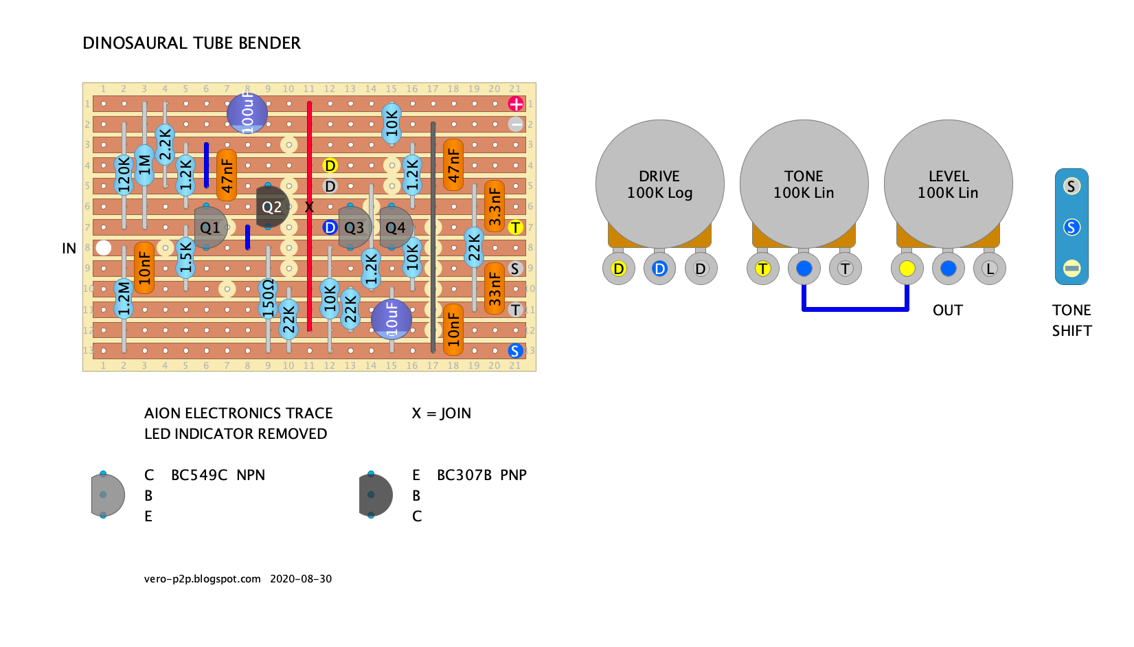
Well, this summer I found one, and after tracing it I can confirm that it is in fact very different from the magazine version. The topology of the schematic is identical, but about half of the resistors and capacitors are different values, and it includes a "Tone Shift" switch to change the operation of the tone control from mostly flat to really scooped.
Here ya go!
Schematic:
Tracing journal here:
https://aionelectronics.com/blog/tracin ... be-bender/
PCB available here:
https://aionelectronics.com/project/wyv ... con-drive/
The magazine version is still a great alternate version for those who want to experiment, and since the schematic is the same, you can of course build the magazine version with the Wyvern PCB if you want.
Well, this summer I found one, and after tracing it I can confirm that it is in fact very different from the magazine version. The topology of the schematic is identical, but about half of the resistors and capacitors are different values, and it includes a "Tone Shift" switch to change the operation of the tone control from mostly flat to really scooped.
Here ya go!
Schematic:
- Dinosaural Tube Bender Schematic (2016 reissue)
https://aionelectronics.com/blog/tracin ... be-bender/
PCB available here:
https://aionelectronics.com/project/wyv ... con-drive/
The magazine version is still a great alternate version for those who want to experiment, and since the schematic is the same, you can of course build the magazine version with the Wyvern PCB if you want.
-
andy-h-h
- Breadboard Brother
Information
Well that might explain why I binned my last attempt at this - updated layout 
-
Ben N
- Cap Cooler
The heart of this thing is the old Differential Distortion DIY circuit from a 1995 PE article.

It is also very similar to Keeley's Fuzz Head. (When I saw Kevin's Trace Journal mention a Fuzz Bender, I thought, "Hey, this doesn't look like the Keeley Fuzz Bender at all," but, no, different Keeley fuzz.)
It is also very similar to Keeley's Fuzz Head. (When I saw Kevin's Trace Journal mention a Fuzz Bender, I thought, "Hey, this doesn't look like the Keeley Fuzz Bender at all," but, no, different Keeley fuzz.)