Nicely done schematic by the way, thank you
Crowther Audio - Prunes & Custard
-
Torchy

Information
Thats the only reason I could think of.
Nicely done schematic by the way, thank you
Nicely done schematic by the way, thank you
-
krome_magnon

- Breadboard Brother
Thanks. Disregarding the sketchy nature of some of the values, does it look like it follows the actual circuit?Torchy wrote:Thats the only reason I could think of.
Nicely done schematic by the way, thank you
I think I've followed it correctly, and the circuit makes sense as drawn.
CP10H brings up all sorts of crap on google, but no real details. I'd say something like a 1N4007 or similar diode would give polarity protection in that spot.
The noise from the tape deck was only drowned out by the buzz from the wine.
-
RLBJR65

- Resistor Ronker
Information
CP104 maybe?
Electronic Devices Inc
Silicon Rectifier
V(RRM)(V) Rep.Pk.Rev. Voltage=1.2k
V(FM) Max.(V) Forward Voltage=2.0
@Temp. (?C) (Test Condition)=25
I(O) Max.(A) Output Current=150m
@Temp (?C) (Test Condition)=100
Electronic Devices Inc
Silicon Rectifier
V(RRM)(V) Rep.Pk.Rev. Voltage=1.2k
V(FM) Max.(V) Forward Voltage=2.0
@Temp. (?C) (Test Condition)=25
I(O) Max.(A) Output Current=150m
@Temp (?C) (Test Condition)=100
-
krome_magnon
- Breadboard Brother
A likely candidate, and I could be right and pretty much any rectifier diode will go in it's place. It's not going to affect the audio path anyway.RLBJR65 wrote:CP104 maybe? ...
The noise from the tape deck was only drowned out by the buzz from the wine.
-
analogguru
- Old Solderhand
Information
Îf there would be written C10PH this would be a zener-diode 10V made by PH-ilips.
analoguru
analoguru
There´s a sucker born every minute - and too many of them end up in the bootweak pedal biz.
-
kusi

- Breadboard Brother
hi guys,
thanks a lot for your work!
@krome_magnon:
i think one of the both 10k resistors at IC1b should be at pin6 of it.
could someone explain the theory behind this kind of clipping? lokks very intressting!
please excuse my english
regards, kusi
thanks a lot for your work!
@krome_magnon:
i think one of the both 10k resistors at IC1b should be at pin6 of it.
could someone explain the theory behind this kind of clipping? lokks very intressting!
please excuse my english
regards, kusi
-
bajaman

- Old Solderhand
Information
- Posts: 4549
- Joined: 26 Jun 2007, 21:18
- Location: New Brighton, Christchurch, NZ
- Has thanked: 596 times
- Been thanked: 2061 times
Hi kimosabi
you are correct
I am still puzzled by the component around the second half of the dual opamp - I cannot see how it can be a 1Meg resistor from the Blacman's gut shot pics. I also thought it was a 390k, but it has an extra band on the body - is it an inductor by chance??
I also have issues with the resistors in the diode chains - I cannot see how the 56k resistor is correct - it looks like 21k to me (how did you measure it Richard - with a digital or analog meter??). The board trace gut shots show that the bottom two diodes and the 16k resistor on Krome Magnum's schem were never fitted as well!!!
I do not think there are three 16k resistors,(only two) - one of them looks more like a 15k to my eyes.
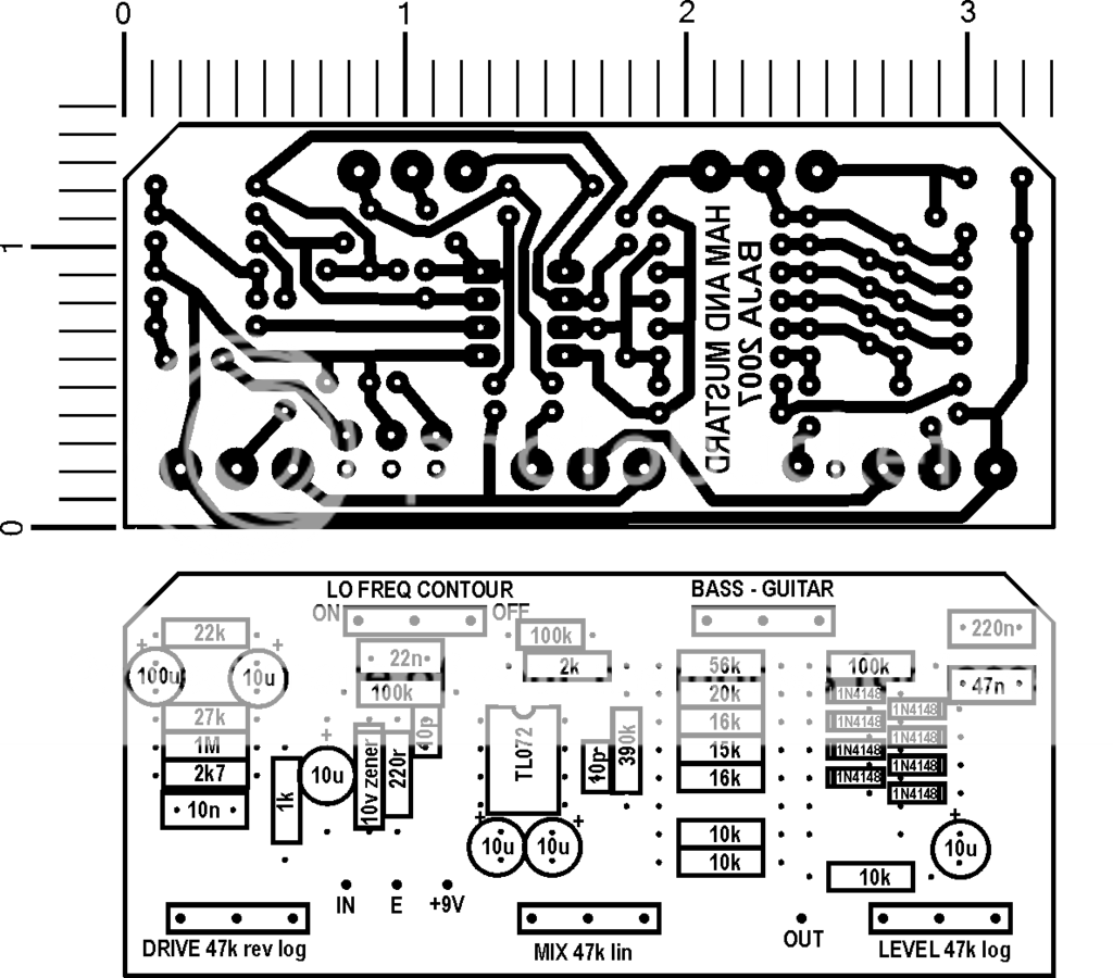
Anyway, I have posted a board layout based on the yellow traces and my guess at the correct values - I will update it once someone can actually verify the correct values
Ham and Mustard PCB and layout
cheers
bajaman[/url]
you are correct
the board trace shows this.think one of the both 10k resistors at IC1b should be at pin6 of it
I am still puzzled by the component around the second half of the dual opamp - I cannot see how it can be a 1Meg resistor from the Blacman's gut shot pics. I also thought it was a 390k, but it has an extra band on the body - is it an inductor by chance??
I also have issues with the resistors in the diode chains - I cannot see how the 56k resistor is correct - it looks like 21k to me (how did you measure it Richard - with a digital or analog meter??). The board trace gut shots show that the bottom two diodes and the 16k resistor on Krome Magnum's schem were never fitted as well!!!
I do not think there are three 16k resistors,(only two) - one of them looks more like a 15k to my eyes.
Anyway, I have posted a board layout based on the yellow traces and my guess at the correct values - I will update it once someone can actually verify the correct values
Ham and Mustard PCB and layout
cheers
bajaman[/url]
-
Bernardduur
- Transistor Tuner
'No more....... loud music.......'
Follow my love for pedals and amps on https://bernardduur.blogspot.com and https://www.instagram.com/bernardduur1
Follow my love for pedals and amps on https://bernardduur.blogspot.com and https://www.instagram.com/bernardduur1
-
bajaman
- Old Solderhand
Information
- Posts: 4549
- Joined: 26 Jun 2007, 21:18
- Location: New Brighton, Christchurch, NZ
- Has thanked: 596 times
- Been thanked: 2061 times
Hi - thanks for the help Bernardduur - it is a 390k 1% resistor 
enjoy the pcb layout
cheers
bajaman
enjoy the pcb layout
cheers
bajaman
-
bajaman
- Old Solderhand
Information
- Posts: 4549
- Joined: 26 Jun 2007, 21:18
- Location: New Brighton, Christchurch, NZ
- Has thanked: 596 times
- Been thanked: 2061 times
After further checking - I now think that the 15k resistor is actually a 75k, and that the 56k is correct too.
-
bajaman
- Old Solderhand
Information
- Posts: 4549
- Joined: 26 Jun 2007, 21:18
- Location: New Brighton, Christchurch, NZ
- Has thanked: 596 times
- Been thanked: 2061 times
Perhaps Richard (theblackman) could measure these resistors and put us out of our misery - somehow, i don't think we are there yet - but getting closer
bajaman
bajaman
-
krome_magnon
- Breadboard Brother
The latest incremental update.

The signal is fed into the second op-amp's inverting input and to that ladder of diodes.
When the signal is strong enough to pass through the first pair of diodes the portion of the signal strong enough to pass is fed to the non-inverting input, and therefore out of phase, with the main signal and cancels out some of the dry signal at the frequencies with enough amplitude to pass through the diodes.
If the signal is strong enough to pass the second pair they are fed to the inverting input and will add back into the original at the frequencies strong enough to get past 2 diode drops.
And so on, add, subtract, add, subtract at the various frequencies and amplitudes of the input signal.
Well spotted, and I've corrected the mistake on the schem.k**i wrote:@krome_magnon:
i think one of the both 10k resistors at IC1b should be at pin6 of it.
Well it looks like...k**i wrote:could someone explain the theory behind this kind of clipping? looks very intressting!
The signal is fed into the second op-amp's inverting input and to that ladder of diodes.
When the signal is strong enough to pass through the first pair of diodes the portion of the signal strong enough to pass is fed to the non-inverting input, and therefore out of phase, with the main signal and cancels out some of the dry signal at the frequencies with enough amplitude to pass through the diodes.
If the signal is strong enough to pass the second pair they are fed to the inverting input and will add back into the original at the frequencies strong enough to get past 2 diode drops.
And so on, add, subtract, add, subtract at the various frequencies and amplitudes of the input signal.
Last edited by krome_magnon on 08 Sep 2007, 14:19, edited 1 time in total.
The noise from the tape deck was only drowned out by the buzz from the wine.
-
bajaman
- Old Solderhand
Information
- Posts: 4549
- Joined: 26 Jun 2007, 21:18
- Location: New Brighton, Christchurch, NZ
- Has thanked: 596 times
- Been thanked: 2061 times
NO
the first op amp has 100k feedback resistor
the second op amp has 390k feedback resistor
Still unsure about that 15k resistor in the diode ladder - it could be a 75k - hopefully theblackman will help us soon.
cheers
bajaman
the first op amp has 100k feedback resistor
the second op amp has 390k feedback resistor
Still unsure about that 15k resistor in the diode ladder - it could be a 75k - hopefully theblackman will help us soon.
cheers
bajaman
-
krome_magnon
- Breadboard Brother
Adjusted accordingly, I'll give it a rest until we get some more evidencebajaman wrote:NO
the first op amp has 100k feedback resistor
the second op amp has 390k feedback resistor
Still unsure about that 15k resistor in the diode ladder - it could be a 75k - hopefully theblackman will help us soon.
cheers
bajaman
The noise from the tape deck was only drowned out by the buzz from the wine.
-
RLBJR65
- Resistor Ronker
Information
krome_magnon I think the schematic is right but I still question some of the values. I cut the board sections from all 5 of the pics and pasted them into 1 pic. Really helped me instead of fliping though them. http://i10.tinypic.com/68mrwcn.jpg
Close pic http://i19.tinypic.com/4mrjc7b.jpg
The 16K resistors look like 20K to me. They are 5 band red black black red brown = 20K - 1%
I'll go along with the 56K if it's 6 band and the green has been scraped off Green blue black red brown red = 56K 1%
I can't tell if that is a 15K or 75K either. Violet? Brown? Looks more black than brown.
Theblackman said he measured the 56k so I assume it's ok. I have doubts about a couple of things. The two 10k resistors coming from +/- of the second opamp to the 10u cap. On the pic they look like red red black black. 220ohms? The 10k resistor from the wiper of the level pot looks like brown black red, 1k.
-
theblackman

- Resistor Ronker
hi guys, when I dismantled the P&C there were a number of components under the goop which had been damaged by my scraping, fortunately only the diodes were broken and easily replaced.
The resistors that you are asking about had some of the markings partially scraped off so I desoldered and measured with a DMM and made sure what was left of the markings agreed with the DMM reading.
And now I have broken my one month forum addiction cold turkey
If you are still unsure, please post an image of the circuit board with a circle around the disputed components and I'll see what I can do about finding their value. Cheers, Rich
-
bajaman
- Old Solderhand
Information
- Posts: 4549
- Joined: 26 Jun 2007, 21:18
- Location: New Brighton, Christchurch, NZ
- Has thanked: 596 times
- Been thanked: 2061 times
Hi theblackman
As I requested in my PM to you, please measure and supply the values for the 6 resistors immediately in a vertical line below the 56k that you have already measured and posted - these values are critical to the circuit's operation, which is why Paul Crowther has scraped the bands of one end of them.
many thanks
bajaman
-
theblackman
- Resistor Ronker
those are the ones I did measure with a DMM and posted them already on page one of this thread