Not yet, I have a hard time to get hold of both the the optocouplers and the active filter chip. I have played with the fuzz section as well and it works fine here. The three resistors from emitter to current rail should be 180k, not 100k ...which transistors did you use? It seems to like higher gain transistors, it sounds best to my ears with three MPSA18's.jrfox92 wrote:Anyone verify it? I breadboarded the fuzz circuit, but it was so gated it just farted out notes.
Death by Audio - Evil Filter [traced]
-
jrfox92

- Breadboard Brother
Information
- Posts: 70
- Joined: 11 Jun 2014, 04:46
- Completed builds: Death by Audio Fuzz War
Electro-Harmonix Big Muff Pi V5
Skreddy Lunar Module
Colorsound Overdriver
Electro-Harmonix Big Muff Pi Multi-Diode and Feedback Mod
Electro-Harmonix Holy Grail Room Reverb and Reverb Length Mod
Boss DS-1 Synth Circuit Bend - Location: Akron, Ohio
- Has thanked: 3 times
- Been thanked: 54 times
Well, my first attempt at the vero seems to be a failure for now. 
So far, only the High Pass filter passes any signal at all.
I messed up the wiring a few times since the whole thing is a bit of a rat's nest because the pcb's I used for the 3PDT switches were unfamiliar and just a general pain in the ass and thus the wires have to go in all sorts of positions. So that might've messed up some components.
Oh well, I guess I'll just build a second one and avoid doing what I did with the first one.
Hopefully the issue was in my wiring rather than the layout itself.
-
jrfox92
- Breadboard Brother
Information
- Posts: 70
- Joined: 11 Jun 2014, 04:46
- Completed builds: Death by Audio Fuzz War
Electro-Harmonix Big Muff Pi V5
Skreddy Lunar Module
Colorsound Overdriver
Electro-Harmonix Big Muff Pi Multi-Diode and Feedback Mod
Electro-Harmonix Holy Grail Room Reverb and Reverb Length Mod
Boss DS-1 Synth Circuit Bend - Location: Akron, Ohio
- Has thanked: 3 times
- Been thanked: 54 times
Alright, after taking off the 3PDT's and putting the transistors in the fuzz and connecting everything, it still sounds awful.
The fuzz is pretty much the same as I described earlier, it has a strong gate so I have to play pretty hard to get that thing going.
The HP filter passes signal pretty much straight through, adjusting resonance cuts out the signal.
The LP and BP filters barely pass signal, but I managed to hear some sound after ramming the fuzz into the filter at the loudest level (which is insanely loud, mind you).
The actual Freq. adjust does nothing.
I don't know if maybe there were some bad connections on the board, or if I fried any of the IC's.
-
jrfox92
- Breadboard Brother
Information
- Posts: 70
- Joined: 11 Jun 2014, 04:46
- Completed builds: Death by Audio Fuzz War
Electro-Harmonix Big Muff Pi V5
Skreddy Lunar Module
Colorsound Overdriver
Electro-Harmonix Big Muff Pi Multi-Diode and Feedback Mod
Electro-Harmonix Holy Grail Room Reverb and Reverb Length Mod
Boss DS-1 Synth Circuit Bend - Location: Akron, Ohio
- Has thanked: 3 times
- Been thanked: 54 times
I DID IT.
IT SOUNDS AWESOME.

I think I burned up the chips on the first one. Because I made the second one almost exactly the same.
For a moment, though, I couldn't get the filter to work, but I realized I didn't ground the board. So, make note of that.
I made a deal with Dan from Satellite Effects where I would do the electronics and he'd make enclosures, so when he gets back from vacation next week and sends me them I'll post a video showcasing all the APTBS riffs you could possibly imagine.
Holy shit, I'm so excited.
Oh, here's what it'll look like.
IT SOUNDS AWESOME.
I think I burned up the chips on the first one. Because I made the second one almost exactly the same.
For a moment, though, I couldn't get the filter to work, but I realized I didn't ground the board. So, make note of that.
I made a deal with Dan from Satellite Effects where I would do the electronics and he'd make enclosures, so when he gets back from vacation next week and sends me them I'll post a video showcasing all the APTBS riffs you could possibly imagine.
Holy shit, I'm so excited.
Oh, here's what it'll look like.
- Attachments
-
Thanks for the trace!jrfox92 wrote:I DID IT.
IT SOUNDS AWESOME.
I think I burned up the chips on the first one. Because I made the second one almost exactly the same.
For a moment, though, I couldn't get the filter to work, but I realized I didn't ground the board. So, make note of that.
I made a deal with Dan from Satellite Effects where I would do the electronics and he'd make enclosures, so when he gets back from vacation next week and sends me them I'll post a video showcasing all the APTBS riffs you could possibly imagine.
Holy shit, I'm so excited.
Oh, here's what it'll look like.
I finished mine today and it rocks!
I really dig the wild filter sweep and the 3 position switch. A very versitale noise maker.
That enclouse looks sweet, did you etch it or did you painted it?
Oh, and how should I wire the expression jack? An expression pedal with this baby should make it even wilder.
Oh, just one more question, how is it going with the DBA Ringmod, any progress?
Once again, thank you, I have to play with it some more-
-
jrfox92
- Breadboard Brother
Information
- Posts: 70
- Joined: 11 Jun 2014, 04:46
- Completed builds: Death by Audio Fuzz War
Electro-Harmonix Big Muff Pi V5
Skreddy Lunar Module
Colorsound Overdriver
Electro-Harmonix Big Muff Pi Multi-Diode and Feedback Mod
Electro-Harmonix Holy Grail Room Reverb and Reverb Length Mod
Boss DS-1 Synth Circuit Bend - Location: Akron, Ohio
- Has thanked: 3 times
- Been thanked: 54 times
dminner/ Satellite Effects from ILF did a couple of acid etched enclosures for me.d312a wrote:That enclouse looks sweet, did you etch it or did you painted it?
Tip goes to expression out, ring doesn't get connected, sleeve goes to ground. Make sure that it's grounded.Oh, and how should I wire the expression jack? An expression pedal with this baby should make it even wilder.
I haven't worked on it lately because I've been dealing a lot with work and the filter, but I'll get around to making a schematic and vero layout soon.Oh, just one more question, how is it going with the DBA Ringmod, any progress?

-
tabbycat
Information
maybe it's even better than that.~arph wrote:Good job guys! Slap a sticker on it and sue DBA when they release it..
maybe they have been too busy touring to commit the necessary time and experimentation required to fully debug and test all their new circuit ideas, so they are accidentally-on-purposely pre-releasing potential ideas via full screen shots of schematics in publicity videos to get the best diy community minds out there to team up and finish the job?
now that would be funny.
think of it this way, if this schematic had produced only-average (or seriously-below-average results) wouldn't the entire circuit-savy dba fanbase out there have piled in with suggestions, fixes and mods, to get it up to scratch and make it sound like what they expect of a great dba? like free debugging, development and market-testing all in one.
because it's 'the new dba' and everyone wants to be the first to own the new dba?
consequently dba sacrifices a few (it's not a beginners build by any standard) sales to a handful of comitted diy homebuilders (trivial sales losses compared to the potential sales gains for a great-sounding official dba release) in return for being able to rebalance their creative lives away from sitting in a solder-fogged basement going debug-mad, and towards spending more time getting kicks on tour and hanging out in the studio.
i'm not saying it's the case, or even probable. but it's not impossible and the thought amused me.
and wouldn't it be a beautiful trick to play on (or with) the diy scene?
-
jrfox92
- Breadboard Brother
Information
- Posts: 70
- Joined: 11 Jun 2014, 04:46
- Completed builds: Death by Audio Fuzz War
Electro-Harmonix Big Muff Pi V5
Skreddy Lunar Module
Colorsound Overdriver
Electro-Harmonix Big Muff Pi Multi-Diode and Feedback Mod
Electro-Harmonix Holy Grail Room Reverb and Reverb Length Mod
Boss DS-1 Synth Circuit Bend - Location: Akron, Ohio
- Has thanked: 3 times
- Been thanked: 54 times
For what it's worth, as much as I love Death by Audio, I doubt I'd ever buy their new filter.
That's mainly due to perceived worth compared to cost. While I think it's probably worth around $200, I imagine they'd sell it for around $300.
Also, there's plenty of other variable filters and high gain fuzzes out there that are much better sounding than this.
It's cool, but there's always room for improvement.
Also, it's seriously ruining my hearing. Be careful because I noticed on the preamp for my RE-20 that there are a lot of inaudible/barely audible but extremely loud sounds that come from the filter due to the resonance.
Keep in mind that I'm saying this yet I bought a Space Ring the instant it came out without having any clue what it sounded like.
It still sounds like shit, by the way.
-
jrfox92
- Breadboard Brother
Information
- Posts: 70
- Joined: 11 Jun 2014, 04:46
- Completed builds: Death by Audio Fuzz War
Electro-Harmonix Big Muff Pi V5
Skreddy Lunar Module
Colorsound Overdriver
Electro-Harmonix Big Muff Pi Multi-Diode and Feedback Mod
Electro-Harmonix Holy Grail Room Reverb and Reverb Length Mod
Boss DS-1 Synth Circuit Bend - Location: Akron, Ohio
- Has thanked: 3 times
- Been thanked: 54 times
So, troubleshooting pt. 3.
I've already gotten everything working, but, after checking, I realized that the expression control doesn't work. In any fashion.
So, that piqued my curiosity. After looking at the schematic, how would the expression control even work given that it doesn't control the same function as the Frequency knob?
Most likely, I'll just change the expression control so it switches out the Frequency knob instead.
How did you make the expression pedal connections? I have the same problem.
Not trying to Necro-Bump this thread, but I had some thoughts about the expression pedal options on this.
looking at the schematic, 9V is supplied to pin 2 of the H11F1M optocoupler through a 1k resistor (R14 and R15) and then comes back "out" through pin 2, through a 10k and then has a path to ground through the C500K Frequency pot. The expression pedal is attached right after the diode supplying power to the H11F1M's, and creates a separate path to ground, though it has no series resistance so it's essentially a short when the pot is as min value. I haven't built the pedal yet, but just for the sake of rapping about it, if you set the Frequency pot at minimum resistance value (0 ohms) the LED's would be at their brightest settings. Then plug in your expression pedal which according to the DBA website is supposed to be a 10k for this particular device, which would then provide a 0-10K resistance path to ground parallel to the other two 11K paths to ground..
For the expression to work correctly does the Frequency pot just need to be set at no resistance (whatever end of the sweep that is) ? And maybe some sort of series resistor is in order here to prevent a total short through the pot ? The expression sweep is really the only function of this device I'm really interested in. The CME video of it is ridonkulous. Want.
-Brett
-
jrfox92
- Breadboard Brother
Information
- Posts: 70
- Joined: 11 Jun 2014, 04:46
- Completed builds: Death by Audio Fuzz War
Electro-Harmonix Big Muff Pi V5
Skreddy Lunar Module
Colorsound Overdriver
Electro-Harmonix Big Muff Pi Multi-Diode and Feedback Mod
Electro-Harmonix Holy Grail Room Reverb and Reverb Length Mod
Boss DS-1 Synth Circuit Bend - Location: Akron, Ohio
- Has thanked: 3 times
- Been thanked: 54 times
After some time away from the circuit, I think the expression wiring would be something comparable to this (where "Vdd" would be your 9V input from the main power and the "ADC input" would be the 9V line to the optocouplers):
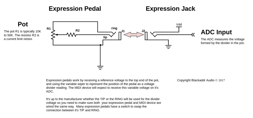
Since I'm pretty sure DBA uses mainly the 5-pin Switched Stereo Jacks in most of their builds, I'd guess that the "switch" connections on the jack would connect to each other, which means they'd disconnect upon insertion of an expression plug.
Though I've built a few of these, I haven't worked on the circuit for a while since H11F1's are expensive to source and I haven't felt like going out of my way to buy them.![[smilie=a_whyme.gif]](./images/smilies/a_whyme.gif "a_whyme")
Since I'm pretty sure DBA uses mainly the 5-pin Switched Stereo Jacks in most of their builds, I'd guess that the "switch" connections on the jack would connect to each other, which means they'd disconnect upon insertion of an expression plug.
Though I've built a few of these, I haven't worked on the circuit for a while since H11F1's are expensive to source and I haven't felt like going out of my way to buy them.
Yeah I was planning on doing exactly what you have shown trying a 1k for the series load resistor when I get to this build.
If it doesn't work, maybe it'll just have to be a modified expression pedal with a 500k pot in it .. yikes
If it doesn't work, maybe it'll just have to be a modified expression pedal with a 500k pot in it .. yikes
Just another smallish update here, It looks as if someone at least has figured out the expression pedal portion of this guy..
https://reverb.com/item/6906852-ftelett ... d-aluminum
If that isn't an Evil Filter clone, well I'd be really surprised. Not sure if anyone cares to chime in on this, I was planning on ordering parts for this in the next week or so.
Thanks for looking
-Brett
https://reverb.com/item/6906852-ftelett ... d-aluminum
If that isn't an Evil Filter clone, well I'd be really surprised. Not sure if anyone cares to chime in on this, I was planning on ordering parts for this in the next week or so.
Thanks for looking
-Brett
It's been a while, anyone had a chance to peek inside one yet? I'd really like to get the expression jack sorted out on this build.
Anyone got a unit to post pics?
Anyone got a unit to post pics?
jrfox92 wrote: ↑13 Sep 2015, 23:16Okay, so, based on the other schematic I found out what the fuzz/filter switches were and how they're connected to each other.jrfox92 wrote:So, I took a screen shot of their computer schematic which seems to have a few extra things going on so I'll try copying it up in the next day or two.
So, the DPDT switch in Glass Hero's schematic is the Fuzz Type switch (I think it acts like the intensity switch on the Harmonic Transformer).
The 3PDT switches are connected together in a slightly hectic fashion (as far as looking at it on a schematic is concerned).
Enjoy.
Hello Sir.
Would you mind sharing the computer schematic please? Im debugging one of those and it has been real PITA
Cheers!!