from our friends at musikding:
ZVEX Box of Rock Schematic
enjoy,
zj
Zvex - Box of Rock [traced]
-
modman

- a d m i n
Information
- Posts: 4898
- Joined: 19 Jun 2007, 16:57
- Has thanked: 4411 times
- Been thanked: 2139 times
- Attachments
-
- Zvex - Box of Rock schematic
Last edited by modman on 23 Jul 2007, 14:24, edited 1 time in total.
-
bajaman

- Old Solderhand
Information
- Posts: 4549
- Joined: 26 Jun 2007, 21:18
- Location: New Brighton, Christchurch, NZ
- Has thanked: 596 times
- Been thanked: 2061 times
Hi friends
One mistake? with the Box Of Crock schematic
The 10n on the tone control should be 100n
Otherwise everything from the drain of the third mosfet to the output would not be the same as the BSIABII
Did you spot the Marshall circuit snippet in there

(470k parallelled with 470pf) a treble boosting filter used by Jim before the great Z was probably born
Back to the Future again AG
Okay then - what is this last mosfet gain stage?
Is it - no it can't be... but..... yes - it is another SHO stage
Cheers Steve
ps: I wonder if he paid any royalties to Ed Guidry and his designer friends for DIRECTLY copying there tone control and output filter design
(that is assuming this schematic is correct!)
One mistake? with the Box Of Crock schematic
The 10n on the tone control should be 100n
Otherwise everything from the drain of the third mosfet to the output would not be the same as the BSIABII
Did you spot the Marshall circuit snippet in there
(470k parallelled with 470pf) a treble boosting filter used by Jim before the great Z was probably born
Back to the Future again AG
Okay then - what is this last mosfet gain stage?
Is it - no it can't be... but..... yes - it is another SHO stage
Cheers Steve
ps: I wonder if he paid any royalties to Ed Guidry and his designer friends for DIRECTLY copying there tone control and output filter design
(that is assuming this schematic is correct!)
-
analogguru

- Old Solderhand
Information
I don´t think so, somebody wrote me this:I wonder if he paid any royalties to Ed Guidry and his designer friends for DIRECTLY copying there tone control and output filter design
The rest is private talk....I found it funny that Zach Vex copied the 'back end' of the BSIAB component-for-component. Is this really correct?
If so, I don't resent it, I posted the schematic, after all. I'm actually kind of flattered that he used it.
analogguru
There´s a sucker born every minute - and too many of them end up in the bootweak pedal biz.
-
briggs

- Tube Twister
Information
I think it's quite funny. Every time you buy a zvx you are basically buying a multiple of the SHO - x2 x3 x4! C'mon Z give us something to get excited about!
-
bajaman
- Old Solderhand
Information
- Posts: 4549
- Joined: 26 Jun 2007, 21:18
- Location: New Brighton, Christchurch, NZ
- Has thanked: 596 times
- Been thanked: 2061 times
I cannot see any layout???
The original schematic at the top of the thread cannot be correct with that 10n in the tone control surely???
I think it needs to be 100n - to match the BSIABII circuit - can someone confirm please!!!
Cheers
Steve
The original schematic at the top of the thread cannot be correct with that 10n in the tone control surely???
I think it needs to be 100n - to match the BSIABII circuit - can someone confirm please!!!
Cheers
Steve

-
invictus

- Breadboard Brother
.
i built this circuit based on the first layout (by FcKw) posted above, i used 100n cap at the tone part...
both the FckW and Igloo's layout is not same as the schematic posted here... (100n tone cap and 47K output resistor)
as soon as somebody verify the actual values used in the commercially available units, i will update the schematic and post it here for everybody's reference.
anyway, the circuit using 100n tone cap sounds quite nice... i didnt try 10n... it sounds...uhmm.... it sounds like 4 cascaded SHOs
with maximum drive at low volume settings, i couldnt get enough grainy distortion, so i tried pushing it with a clean boost from the eternity clone i built recently... there, im satisfied...
.. thanks guys for the info. someone please verify the actual values so we could update the schematic posted.
.
-
analogguru
- Old Solderhand
Information
100n seems to be the correct value for the tone control.... This would fit to the BSIAB II.... but who knows ? In boutique-pedals you can find many things.... sometimes also cloning-mistakes. I know one unit which was sold for years as a 100% clone, until the builder found one of my schematic... Now the unit has been updated
If the Zvex Octane schematic shows the real content of the unit, then i assume, Zvex never has seen a real unit, only the printed schematic which contains mistakes. Also the printed Kay Fuzztone schematic supplied with the unit is incorrect. If you take this schematic for cloning...it wil never be a real clone. Sunn Buzz factory schematic is incorrect....the list can be continued.
Since the output capacitor is 10µF (nobody knows why) it doesn´t make a difference to the unit itself if the output resistor is 47k or 100k. (even with only 47k the LF-response will be linear down to approx. 2 Hz and the load difference on the output stage is neglicible). Maybe it can have an influence on the following guitar amp if this guitar amp has no DC-decoupling and no 68k input resistors.....only then.
analogguru
There´s a sucker born every minute - and too many of them end up in the bootweak pedal biz.
-
analogguru
- Old Solderhand
Information
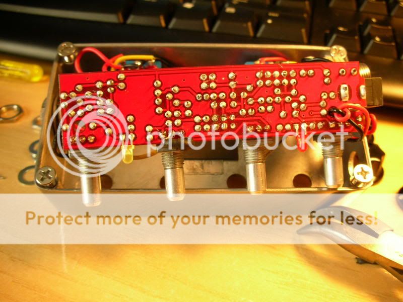
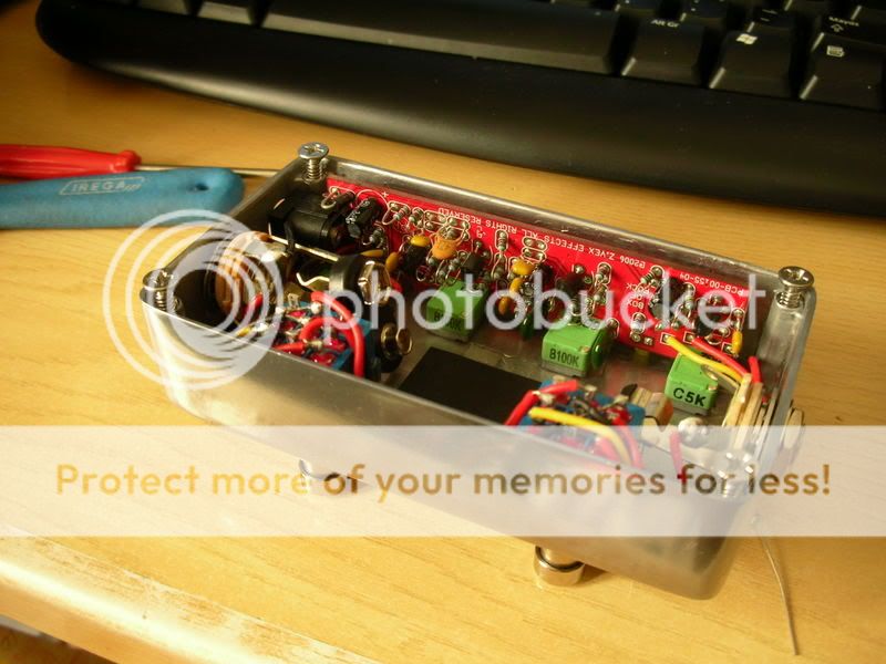
Here are some guts:
http://f.hatena.ne.jp/toy_love/20061120163005
http://f.hatena.ne.jp/toy_love/20061121042043
http://f.hatena.ne.jp/toy_love/20061120163207
http://f.hatena.ne.jp/toy_love/20061120162105
http://f.hatena.ne.jp/toy_love/20061120162208
http://f.hatena.ne.jp/toy_love/20061120162155
analogguru
http://f.hatena.ne.jp/toy_love/20061120163005
http://f.hatena.ne.jp/toy_love/20061121042043
http://f.hatena.ne.jp/toy_love/20061120163207
http://f.hatena.ne.jp/toy_love/20061120162105
http://f.hatena.ne.jp/toy_love/20061120162208
http://f.hatena.ne.jp/toy_love/20061120162155
analogguru
There´s a sucker born every minute - and too many of them end up in the bootweak pedal biz.
-
Goop_buster

- Solder Soldier
and anotheranalogguru wrote:Here are some guts:
http://f.hatena.ne.jp/toy_love/20061120163005
http://f.hatena.ne.jp/toy_love/20061121042043
http://f.hatena.ne.jp/toy_love/20061120163207
http://f.hatena.ne.jp/toy_love/20061120162105
http://f.hatena.ne.jp/toy_love/20061120162208
http://f.hatena.ne.jp/toy_love/20061120162155
analogguru
http://www.proguitar.de/ProGuitarPreisl ... InnenK.jpg
but not much to see
- Attachments
-
- 20061120163005.jpg (45.88 KiB) Viewed 14325 times
-
- 20061120162105.jpg (28.28 KiB) Viewed 14325 times
-
- 20061120163207.jpg (28.05 KiB) Viewed 14325 times
-
- 20061121042043.jpg (32.37 KiB) Viewed 14325 times
-
madbean
Information
I've got a verified pcb layout of the dirt side of the schematic (I didn't put the boost in) if anyone is interested and it's kosher. I've built it but not boxed it so it's verified.

-
markm
- Diode Debunker
Nice!madbean wrote:I've got a verified pcb layout of the dirt side of the schematic (I didn't put the boost in) if anyone is interested and it's kosher. I've built it but not boxed it so it's verified.
I was going to do mine without the boost too.
-
briggs
- Tube Twister
Information
Nice stuff bean, very clean layout! When are you releasing your stuff? Can we have a go at de-gooping that

I am Klon.
I like post #55 from the HC thread:
Maybe that'll be the next design - just keep adding SHOs!I know it is more ££'s, etc, but a Super Duper 2 in 1 (or a SHO) in front of the Box of Rock is a wonderful thing. The BoR responds wonderfully to it, and really does give you full on gain that is controllable from your volume.