A gift from one of our friends at Das Musikding. Not mine to post so I'll link. Maybe someone would like to take a shot and redraw in some nice CAD layout.
Mad Professor Little Green Wonder
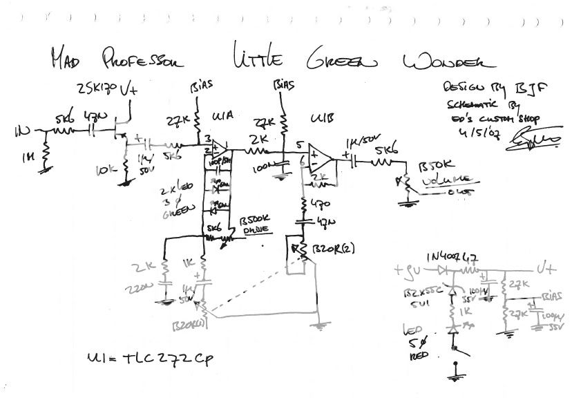
Mad Professor - Little Green Wonder
-
The Rotagilla

- Diode Debunker
-
bajaman

- Old Solderhand
Information
- Posts: 4549
- Joined: 26 Jun 2007, 21:18
- Location: New Brighton, Christchurch, NZ
- Has thanked: 596 times
- Been thanked: 2061 times
IC is TLC2272CP ????
IC is a TLC 272CP, nothing special, even my local radio shack has it in stock.
BTW: The BIAS supply for the FET is not drawn on the schem, maybe the buffer will work w/o it, but IMHO the gate needs a fixed BIAS voltage.
JHS
BTW: The BIAS supply for the FET is not drawn on the schem, maybe the buffer will work w/o it, but IMHO the gate needs a fixed BIAS voltage.
JHS
I was wondering the same thing myself!!JHS wrote:IC is a TLC 272CP, nothing special, even my local radio shack has it in stock.
BTW: The BIAS supply for the FET is not drawn on the schem, maybe the buffer will work w/o it, but IMHO the gate needs a fixed BIAS voltage.
JHS
It's highly likely that the JFET will bias up to a few volts with no external bias supply. They self-bias in the same manner as triodes.JHS wrote:BTW: The BIAS supply for the FET is not drawn on the schem, maybe the buffer will work w/o it, but IMHO the gate needs a fixed BIAS voltage.
JHS
-
bajaman
- Old Solderhand
Information
- Posts: 4549
- Joined: 26 Jun 2007, 21:18
- Location: New Brighton, Christchurch, NZ
- Has thanked: 596 times
- Been thanked: 2061 times
Sometimes they do not - I was putting a buffer in a pedal last night - dropped a 1M resitor to ground and got 0.6v dc at the source. So I connected the resistor to half rail (4.5v) and it biased up at 5.1v dc - ideal.It's highly likely that the JFET will bias up to a few volts with no external bias supply. They self-bias in the same manner as triodes.
bajaman
bajaman
-
BJF

- Resistor Ronker
Hi,
Yes, IC is TLC 272, chosen becuase it distorts in a nice way below the limt of the green LED's also those picked for desired level.
Hm, yes ofcourse a bias is needed for the input buffer and what's missing is a 1M Ohm resistor from gate of the 2SK170 to the midpoint bias supply.
There are a couple of things in the design that limits some distortions some like loading distortion.
Have fun
BJ
BJF Electronics
Sweden
-
bajaman
- Old Solderhand
Information
- Posts: 4549
- Joined: 26 Jun 2007, 21:18
- Location: New Brighton, Christchurch, NZ
- Has thanked: 596 times
- Been thanked: 2061 times
Hi BJF - thanks for clarifying the fet bias error on the schematic - it looks like an interesting design to me too 
bajaman
bajaman
This is a one of the nicer overdrives I've tried. And BJF is a quite a gentleman.
-
seniorLoco

- Resistor Ronker
but why do i still prefer my mij SD1 
Hi ya ...nice to see you felas here !
Hi ya ...nice to see you felas here !
-
BJF
- Resistor Ronker
Hi,seniorLoco wrote:but why do i still prefer my mij SD1
Hi ya ...nice to see you felas here !
Perhaps because you'd like more compression and more treble.
When the LGW was released some of the diehard TS guys bought it and they were very displeased and would have been much happier with the Blues Devil.......pounding their strats with hairy boots
LGW was made for those that really not could get along with standards
and the idea of it came to me in a request of what a BJF TS style would sound like and the guy told me he'd run a fuzz into TS's to smooth things....and so I wonder why would anyone do that as it would bring funny little artifacts ontop of sound aswell as cut all the lowmids and bass-oh yes I got this tested and listened and understood but still, and you know if headroom was higher this could be avoided and the basic filtering to the treble and then you could also use it with humbuckers and P-90's.......
If somebody would do the honours and post a schematic with a basic Tubescreamer in the DIY section with just numbers on the components I might explain a few things more clearly.
Have fun
BJ
Just so I'm clear on this: the missing 1M resistor connects the gate to Vref (BIAS on the schem) in order to get 4.5v (=9.0/2) on the JFET's drain, right?
And while I'm at it, does anyone know where to find Alpha or similar 20k dual-ganged pots? Smallbear and Mouser don't seem to have them.
And while I'm at it, does anyone know where to find Alpha or similar 20k dual-ganged pots? Smallbear and Mouser don't seem to have them.
-
bajaman
- Old Solderhand
Information
- Posts: 4549
- Joined: 26 Jun 2007, 21:18
- Location: New Brighton, Christchurch, NZ
- Has thanked: 596 times
- Been thanked: 2061 times
YesJust so I'm clear on this: the missing 1M resistor connects the gate to Vref (BIAS on the schem) in order to get 4.5v (=9.0/2) on the JFET's drain, right?
And while I'm at it, does anyone know where to find Alpha or similar 20k dual-ganged pots? Smallbear and Mouser don't seem to have them.
Try futurlec.com
cheers
bajaman
-
The Rotagilla
- Diode Debunker
I can do it first thing tomorrow morning. Did you want a TS-808, TS-9 or TS-10?BJF wrote:If somebody would do the honours and post a schematic with a basic Tubescreamer in the DIY section with just numbers on the components I might explain a few things more clearly.
-
seniorLoco
- Resistor Ronker
Yes BJ ... i see ...
Have tweaked heavily on op amp clippers and got bored .... fuzz lover now and looks like a long term relationship
Recently openhaus got me kinda four op amps- no clippers sounds like a dual crowther ... huge sounding tho.
Have tweaked heavily on op amp clippers and got bored .... fuzz lover now and looks like a long term relationship
Recently openhaus got me kinda
-
BJF
- Resistor Ronker
Hi,The Rotagilla wrote:I can do it first thing tomorrow morning. Did you want a TS-808, TS-9 or TS-10?BJF wrote:If somebody would do the honours and post a schematic with a basic Tubescreamer in the DIY section with just numbers on the components I might explain a few things more clearly.
Thanks,
Oh,any of the above would do.If you can something that incorporates all would be best. I was thinking one could discuss the whys of such a classic design and then absolute values are of little consequence.
Like why would a typical threshold be choosen and why would you like to adjust that and when?
Why would a certain frequency response be desired and why would this be subject to desired change and if so in what range?
Analyzing the circuit would give answers to specific solutions.
One could also look at history and why such a circuit would evolve in the first place.......
Anyway could make fun conversation
Have fun
BJ
-
BJF
- Resistor Ronker
Hi,seniorLoco wrote:Yes BJ ... i see ...
Have tweaked heavily on op amp clippers and got bored .... fuzz lover now and looks like a long term relationship
Recently openhaus got me kinda
Uh yes bored is the word;)I've a long time liked fuzz and distortion more than overdrive mainly because I'd use that only when a clean sound would also be needed from amp or I'd just run ampdistortion.
I don't really need an OD to get a little more gain from amplifier as that is easily set on amp to begin with-sometimes though certain guitars would like a little push;)
Have fun
BJ
-
analogguru

- Old Solderhand
Information
Ok....for THIS sacred purpose we should do it really - Here it is... the first time in internet history.... A high resolution, cleaned up, readableIf somebody would do the honours and post a schematic with a basic Tubescreamer in the DIY section with just numbers on the components I might explain a few things more clearly.
...
Analyzing the circuit would give answers to specific solutions.
One could also look at history and why such a circuit would evolve in the first place.......
Anyway could make fun conversation
Have fun
BJ
Original Ibanez TS-808 factory schematic
enjoy,
analogguru
Last edited by analogguru on 07 Nov 2007, 10:39, edited 1 time in total.
There´s a sucker born every minute - and too many of them end up in the bootweak pedal biz.