Landgraff - MO-D
-
jakerandall

- Breadboard Brother
Information
- Posts: 56
- Joined: 03 Nov 2007, 09:46
wow. thats a mouthful 
http://www.phpbbserver.com/freestompbox ... stompboxes
The schematic has already been posted and discussed. For some reason,
it doesn't show up in a search. Regardless, there you go.
The schematic has already been posted and discussed. For some reason,
it doesn't show up in a search. Regardless, there you go.
-
analogguru
- Old Solderhand
Information
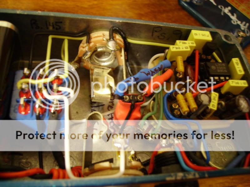
Guts:
http://www.mikigakki.com/img_system/MOD%20DISTORTION_1
http://www.mikigakki.com/img_system/MOD%20DISTORTION_2
http://www.mikigakki.com/img_system/MOD%20DISTORTION_3
analogguru
http://www.mikigakki.com/img_system/MOD%20DISTORTION_1
http://www.mikigakki.com/img_system/MOD%20DISTORTION_2
http://www.mikigakki.com/img_system/MOD%20DISTORTION_3
analogguru
There´s a sucker born every minute - and too many of them end up in the bootweak pedal biz.
-
analogguru
- Old Solderhand
Information
Are you familiar with the terms "mojo" and "misleading confusion" ?I have to ask - what is that coiled orange wire doing the the lower right corner of pic #3?
analogguru
There´s a sucker born every minute - and too many of them end up in the bootweak pedal biz.
-
guiltyspark
- Solder Soldier
That's the + of the battery snap wrapped around the - to be specific-celadine wrote:I have to ask - what is that coiled orange wire doing the the lower right corner of pic #3?
Guiltyspark
can you guys tell me if I wanted to build a landgraff do I need this stuff ?
Landgraff uses AVX metal caps, tantal electrolytic cap for decoupling and Mica for the pF caps.
All Rs are CC and there is a on/off/on switch for selecting 2 diodes, 3 diodes and none
What readily available parts can I buy and use that will get me there or get me close?
Also I notice on the landgraff its a 3 position switch. The up position is? The middle position is? The bottom position is? meaning which diode setup is each position of the switch?
Hi sosodef,sosodef wrote: Also I notice on the landgraff its a 3 position switch. The up position is? The middle position is? The bottom position is? meaning which diode setup is each position of the switch?
As JHS mentioned above, the switch is there to select three different clipping modes. One position is stock Rat, with two diodes for symetrical clipping. The middle position is a diode bypass, and the other position selects three diodes for asymetrical clipping.
-
celadine

- Solder Soldier
That's the + of the battery snap wrapped around the - to be specific-
Guiltyspark
-
soulsonic

- Old Solderhand
Information
Yeah, wrapping a wire that's grounded on one end around the input wire can work well as a tiny RF supression cap. You can also do a similar trick by connecting a wire to the Collector/Drain/Plate of a Transistor/FET/Tube and wrap it around the wire that connects to the Transistor/FET/Tube's input to create some RF-range negative feedback. Can help with stability in some tricky circuits.celadine wrote:That's the + of the battery snap wrapped around the - to be specific-
GuiltysparkWrapping ground around one of the in/out wires may have made sense, in a functional way... Thats just odd.
But that's not what's being done here....
-
bajaman

- Old Solderhand
Information
- Posts: 4549
- Joined: 26 Jun 2007, 21:18
- Location: New Brighton, Christchurch, NZ
- Has thanked: 596 times
- Been thanked: 2061 times
Slightly off topic, but Soulsonic reminds me of a simple way to make a 2pf - 5pf capacitor (sometimes useful to tame rf instability).
Just take a couple of pieces of insulated hookup wire about 10mm in length. Twist them together after stripping the insulation off one end of each piece - 3 twists should do fine. Voila a cheap rf suppression capacitor
If you want a larger capacitance use two 20 mm lengths
cheers
bajaman
Just take a couple of pieces of insulated hookup wire about 10mm in length. Twist them together after stripping the insulation off one end of each piece - 3 twists should do fine. Voila a cheap rf suppression capacitor
If you want a larger capacitance use two 20 mm lengths
cheers
bajaman
-
modman

- a d m i n
Information
- Posts: 4897
- Joined: 19 Jun 2007, 16:57
- Has thanked: 4410 times
- Been thanked: 2139 times
Great! This should go into the Bush Electronics sectionbajaman wrote:Slightly off topic, but Soulsonic reminds me of a simple way to make a 2pf - 5pf capacitor (sometimes useful to tame rf instability).
Just take a couple of pieces of insulated hookup wire about 10mm in length. Twist them together after stripping the insulation off one end of each piece - 3 twists should do fine. Voila a cheap rf suppression capacitor
If you want a larger capacitance use two 20 mm lengths
cheers
bajaman
Please, support freestompboxes.org on Patreon for just 1 pcb per year! Or donate directly through PayPal
-
Greg

- Old Solderhand
Mine does the same thing.neilnil wrote:I recently built one with this schem and yes I've never played around with a real Mo'd pedal but it sounded too bassy when drive is set over 12:00 even with filter knob turned fully ccw. With 30pF as in a stock Rat it sounded ok but seemed to lose some of its character in midrange so I put 51pF back and messed with filter pot to have about 700 to 60k instead of 1.5k to 101.5k and it worked better for me.
Jun
It sounds great everywhere else, but it gets Bassy with the Drive up high.
I was thinking this was due to the low Slew Rate affecting the high frequencies.
Anyone agree ?
If that's the case, a higher value on the Compensation Cap would make it worse.
-
Lovepedal Detective
- Breadboard Brother
Adjusting the input cap can really help with the low end in this circuit.
I have a pic of my Landgraff I will post.
after my 5th post.

-
analogguru
- Old Solderhand
Information
God bless you .....
analogguru
analogguru
There´s a sucker born every minute - and too many of them end up in the bootweak pedal biz.
Are you being sarcastic? Here's another one if not:
-
analogguru
- Old Solderhand
Information
who ? ....me ?Are you being sarcastic?
Thanks for the pictures anyway,
Jesus is lord,
analogguru
There´s a sucker born every minute - and too many of them end up in the bootweak pedal biz.