After reading Jack's excellent article on True Bypass I am surprised to see a pull down resistor in there as well as the current limiting resistor. For any one interested in the article its over on his Mr Black site under the "Straight Jive" menu. A great read for anyone that has not yet read it.
It's fairly straight forward, if you want to start it , press start. You can work out the rest of the controls for yourself !
No silicon heaven ? preposterous ! Where would all the calculators go ?
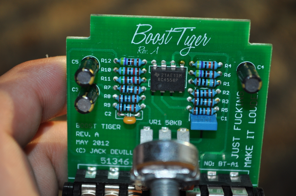
Boost Tiger is a fantastic clean booster / pre-amp.
Currently in production: Rev B1.
Now you have a clean, complete schematic. Build one for yourself and rock.
Attachments
Mr. Black Boost Tiger Rev. B1 Schematic
I'm a "professional."
Buy my products and make me rich.
marshmellow wrote:Ole Jack sure has come a long way since then.
Quite a different circuit, although kudos! There are opamps in both.
I see, you now vary the feedback resistor, those three years of research have been well spent. And you finally did take my advice regarding the bias buffering, my hat's off to you . Or does the ingenuity lie in the split resistor arrangement on the input and output?
You got a bone to pick? Go buy a roast chicken.
Upset for some reason? Perhaps you should take some time to reflect on your life. I don't have time for you.
I'm a "professional."
Buy my products and make me rich.
Jack Deville wrote:Maybe you should think about why it might be there.
I can't see how the 3PDT is wired up in the picture so maybe you not using that bypass system on this pedal ? or switch bounce is still causing a little pop without s pulldown resistor there ? I need enlightened.
Edited after noticing the post above , I just seen you posted the official schem with the switch in so it is that input grounding type series current resistor bypass typo thing. Thanks for showing us all that.
Extra - I managed to get a tunnelworm imported from USA last week. sounds great.
It's fairly straight forward, if you want to start it , press start. You can work out the rest of the controls for yourself !
No silicon heaven ? preposterous ! Where would all the calculators go ?
Jack Deville wrote:You got a bone to pick? Go buy a roast chicken.
Upset for some reason? Perhaps you should take some time to reflect on your life. I don't have time for you.
Yeah, maybe better spend your time studying a book on electronics every once in a while instead, because what I had to read on your tech blog (or whatever you want to call it) today is rather alarming. For naming yourself the "effects wizard" you seem to be remarkably ignorant concerning some basic principles. Like the distinction between current and voltage, for instance. You use the terms practically synonymously and throw them around like there is no tomorrow. And so on...
Can someone help explain the reason for the 1k resistors at the input and output, just seems unique to me and would like to learn.
Also, I do not have any 56k resistors, can someone explain what they are doing in this circuit, are they just voltage dividers?


.