Hello!
Anybody had a chance to get a hold of one of those? Or at least any ideas at what the circuit might resemble?
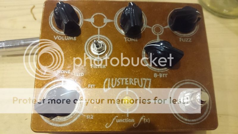
This fuzz box sounds massive!
Here's a PGS demo:
Function f(x) Clusterfuzz [traced]
-
Nocentelli

- Tube Twister
Information
- Posts: 2222
- Joined: 09 Apr 2009, 07:06
- Location: Leeds, UK
- Has thanked: 1155 times
- Been thanked: 954 times
It does sound good: Hopefully someone will get hold of one soon, and culturejam has stayed true to his principles:
https://www.freestompboxes.org/viewtopic ... =Schematicculturejam wrote:Another thing I've frequently said I would do if I started a pedal business is ship a schematic with each pedal.
Lovepedal or the next guy to copy and under-cut is going to work out the circuit anyway. And it's nice to have a schematic on hand for repair or just general information. There's nothing that needs to be hidden. And there's nothing that can be hidden, so I see no reason not to include a schematic in the box.
modman wrote: ↑ Let's hope it's not a hit, because soldering up the same pedal everyday, is a sad life. It's that same ole devilish double bind again...
-
tabbycat

Information
thread at tgp http://www.thegearpage.net/board/index. ... x.1595793/
https://i1283.photobucket.com/albums/a5 ... g~original they've also got one at stompboxclub if you are us based and want to borrow one for the weekend:
http://www.stomp.club/function-f-x--clusterfuzz.html
https://i1283.photobucket.com/albums/a5 ... g~original they've also got one at stompboxclub if you are us based and want to borrow one for the weekend:
http://www.stomp.club/function-f-x--clusterfuzz.html
-
TV-Set

- Breadboard Brother
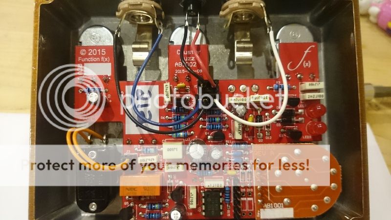
molex pcb connectorsEBRAddict wrote:Any idea what those black connectors are on the 1/4" jacks, DC and footswitch wiring?
-
electrosonic

- Breadboard Brother
Is that mictester's relay switching scheme in the lower left corner?
I see a spst, relay, 2 transistors, a small ignal diode, an electro cap and a couple of resistors.
Ie https://www.freestompboxes.org/viewtopic ... 13&t=13295
Andrew.
I see a spst, relay, 2 transistors, a small ignal diode, an electro cap and a couple of resistors.
Ie https://www.freestompboxes.org/viewtopic ... 13&t=13295
Andrew.
Premier Guitar does a fairly detailed review. I think it's 2 we'll known circuits cascaded. But that's just a wild guess.TV-Set wrote:Hello!
Anybody had a chance to get a hold of one of those? Or at least any ideas at what the circuit might resemble?
This fuzz box sounds massive!
Here's a PGS demo:
-
skywise
- Breadboard Brother
There is also a micro-controller.electrosonic wrote:Is that mictester's relay switching scheme in the lower left corner?
I see a spst, relay, 2 transistors, a small ignal diode, an electro cap and a couple of resistors.
-
Nocentelli
- Tube Twister
Information
- Posts: 2222
- Joined: 09 Apr 2009, 07:06
- Location: Leeds, UK
- Has thanked: 1155 times
- Been thanked: 954 times

modman wrote: ↑ Let's hope it's not a hit, because soldering up the same pedal everyday, is a sad life. It's that same ole devilish double bind again...
-
Nocentelli
- Tube Twister
Information
- Posts: 2222
- Joined: 09 Apr 2009, 07:06
- Location: Leeds, UK
- Has thanked: 1155 times
- Been thanked: 954 times
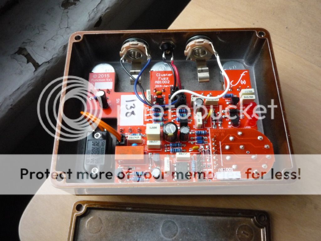
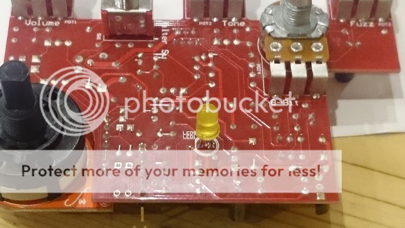
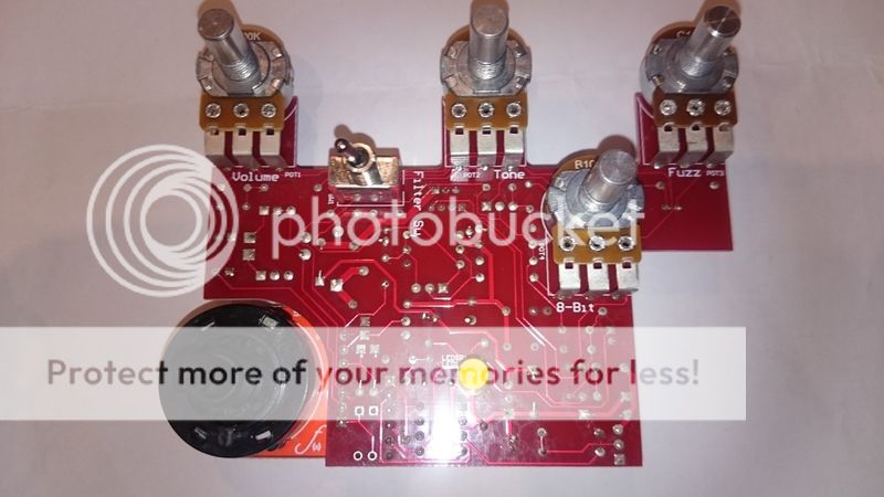
I ordered this pedal late last saturday afternoon, and it had arrived when i got back from work on monday. I played through it for 20 minutes or so, then popped the back off to have a go at tracing it. The molex connectors for in/out, power/ground and footswitch connections made it super easy to completely remove the pcb with zero risk of damage, and i then spent a couple of hours turning it over and over in my hands, peering at the traces and components through a magnifying glass to sketch out a schematic. Most traces are clearly visible, although they are tightly bunched at the top edge of the pcb by the pots, and some pass between the lugs of the filter switch.
All box caps values are clearly visible, but the electro's and ceramics are not all clear due to their positions. However, i found a photo on facebook of the parts stash used to build the pcbs, which made cross checking the parts values a little easier. For example, the big electro in the power line is likely to be 220u, and the ground cap at the input may be the 100p or 680p. The other parts that don't appear in my schematic are from the relay-based true bypass switching, which i didn't bother tracing. I tried to take some shots of the pcb, but artificial light and a crappy camera phone means they're not great and also too big to host here. Next time we get a decent bright day here in the UK (maybe April?), I'll try and convince my wife to take some decent pics with her fancy camera.
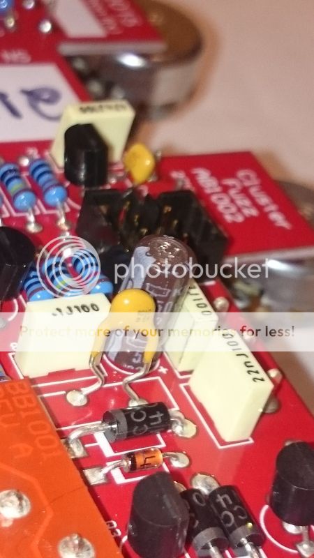
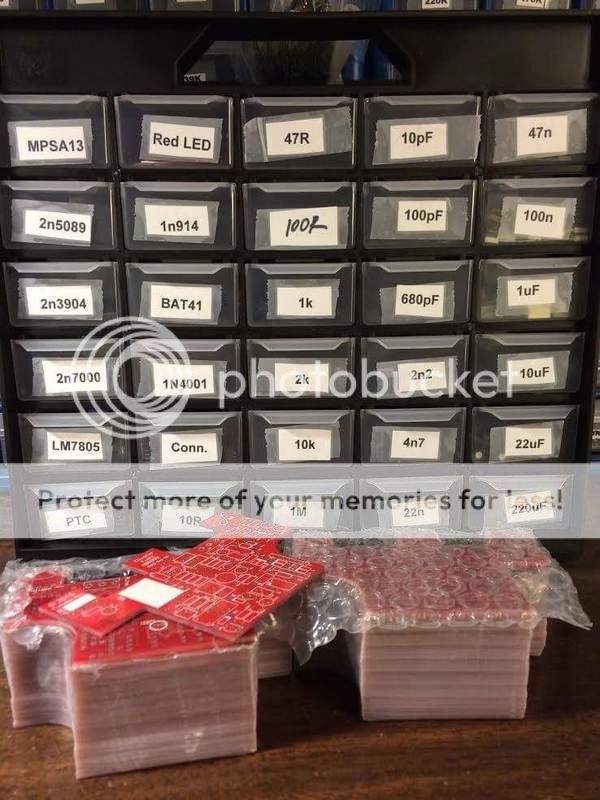
All box caps values are clearly visible, but the electro's and ceramics are not all clear due to their positions. However, i found a photo on facebook of the parts stash used to build the pcbs, which made cross checking the parts values a little easier. For example, the big electro in the power line is likely to be 220u, and the ground cap at the input may be the 100p or 680p. The other parts that don't appear in my schematic are from the relay-based true bypass switching, which i didn't bother tracing. I tried to take some shots of the pcb, but artificial light and a crappy camera phone means they're not great and also too big to host here. Next time we get a decent bright day here in the UK (maybe April?), I'll try and convince my wife to take some decent pics with her fancy camera.


modman wrote: ↑ Let's hope it's not a hit, because soldering up the same pedal everyday, is a sad life. It's that same ole devilish double bind again...
-
Nocentelli
- Tube Twister
Information
- Posts: 2222
- Joined: 09 Apr 2009, 07:06
- Location: Leeds, UK
- Has thanked: 1155 times
- Been thanked: 954 times
modman wrote: ↑ Let's hope it's not a hit, because soldering up the same pedal everyday, is a sad life. It's that same ole devilish double bind again...
-
culturejam

- Old Solderhand
Information
That looks correct, but I don't have the production schematic in front of me.
Nice work! Although it's constructed in a way that makes assembly/disassembly quite easy, and as I recall, all the traces are on one side, both of which make tracing a lot easier than, say, something from Death By Audio.
Nothing hidden, no goop or that sort of tomfoolery.
Hope you guys enjoy it. Brian, Dave, and I had a lot of fun designing it.
Note: there are a few
Nice work!
Nothing hidden, no goop or that sort of tomfoolery.
Hope you guys enjoy it. Brian, Dave, and I had a lot of fun designing it.
Note: there are a few
-
culturejam
- Old Solderhand
Information
So what did you think of the sound? I know that tone is far less important here than resistors, but I thought I'd ask. 
-
johnk
- Resistor Ronker
i just finished building one today and i dig it.
here's the PCB layout that i drew up for it:
and here's the PCBs in a pdf file:
http://johnkvintageguitars.homestead.co ... z_PCBs.pdf
here's the PCB layout that i drew up for it:
http://johnkvintageguitars.homestead.co ... z_PCBs.pdf
Information
Awesome, John! I like your PCB layouts. They etch beautifully. I'll have to give this one a go.johnk wrote:i just finished building one today and i dig it.
here's the PCB layout that i drew up for it:
and here's the PCBs in a pdf file:
http://johnkvintageguitars.homestead.co ... z_PCBs.pdf
Loe Sounds