Thanks for that marshmellow. Think the bandwidth is 200hz to 15k on that transformer. I'll give it a try without the transformer and see what happens while I wait for the transformers to arrive. Bit of an odd design for what it appears to do.marshmellow wrote:Yes, you can build it without the transformer. But it's not in the circuit to provide isolation (as drawn it doesn't), it is there to form the sound. In comparison to an overdriven guitar sound, transformer distortion is very subtle, its contribution might be minimal anyway. These little transformers usually also have very limited bandwidth, so to mimic the sound of the original pedal, you will probably have to introduce at the very least some bass cut.
Hudson - Electronic Broadcast [traced]
-
andy-h-h

- Breadboard Brother
Information
-
Intripped

- Cap Cooler
hello,
i'm ordering some parts from Banzai music and Musikding, and i see that they sell germanium transistors as well; they also offer some kind of hfe selection.
i would like to buy a couple of transistors to try in this circuit, but i really need some help in the choice.
what transistor would you buy? what Hfe?
here are the links, i thank you in advance for your help:
https://www.musikding.de/Germanium-Transistors
https://www.banzaimusic.com/Germanium-Transistors/
https://www.banzaimusic.com/Transistors ... -selected/
-
teddeeh

- Breadboard Brother
Any info on the dual? I have one ordered so should arrive next month after speaking to andertons yesterday. The last batch they only got 50 and i am no. 54 on the list. So no.4 if this batch dosent have extras.
-
andy-h-h
- Breadboard Brother
Information
Hello,
Can anyone explain to me where the filtering is happening between the output of Q2 and the transformer? I have something pretty close to full range up to the 15k resistor, and a fair bit of bottom end drops away after that. I've tried working out where the filtering is happening, but my calculations are clearly wrong, as they don't account for what I'm hearing and seeing on the spectrum analyser.
Using JohnK's vero / schematic.
Thanks
- Attachments
-
Last edited by andy-h-h on 18 Sep 2018, 09:25, edited 1 time in total.
-
andy-h-h
- Breadboard Brother
Information
Hello - The low end drop-off is happening before the transformer. I can take signal from after the 10uf capacitor, but before the 15k resistor, and it's full-range. After the 15k resistor, and the low end has disappeared somewhat. I just updated the schematic above to show where the filtering is happening. Maybe it's related to the transformer, but it seems to be happening before it.plush wrote:Did you consider checking the frequency range of the transformer (ty-141p)?andy-h-h wrote:Hello,
fair bit of bottom end drops away after that
-
plush

- Cap Cooler
andy-h-h wrote:Hello - The low end drop-off is happening before the transformer. I can take signal from after the 10uf capacitor, but before the 15k resistor, and it's full-range. After the 15k resistor, and the low end has disappeared somewhat. I just updated the schematic above to show where the filtering is happening. Maybe it's related to the transformer, but it seems to be happening before it.plush wrote:Did you consider checking the frequency range of the transformer (ty-141p)?andy-h-h wrote:Hello,
fair bit of bottom end drops away after that
-
andy-h-h
- Breadboard Brother
Information
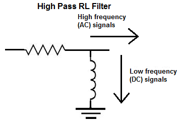
Thanks Plush, I was completely unaware of this kind of filter. 
So one side of the transformer is providing inductance, resulting in a filter when combined with the resistor. I'll have a play with some resistor values and see what happens.
So one side of the transformer is providing inductance, resulting in a filter when combined with the resistor. I'll have a play with some resistor values and see what happens.
-
teddeeh
- Breadboard Brother
So i got my dual hudson in the post today
Here are images of the top and underside of the board.
If anyone wants to trace i will do my best to measure the parts or give readings etc.
That is im assuming a suppression cap on the dc in. The markings say “R005 B8RS”
Trimmers are both 102
Smallest elec cap 10uf @50v
Next size 100uf 25v x3
Second largest size 330uf @16 v (in the middle and this is a 24v pedal..? ) And the second is a 120uf on the right @25 v
Biggest badboy is a 220uf @35v
-
andy-h-h
- Breadboard Brother
Information
This might help - just adjust the power to 9v to have a look around on the sim via the link below. I built one and I quite like it, too lazy to pull it apart and measure voltages though.Brazdj wrote:Hello,
Would someone be kind enough to post transistor voltages for 9v please? I’m also interested in how the transistor voltages change when the gain pot is fully maximized and minimized.
Thanks in advance,
Daniel
Simulated values @ 9v. The simulated vales at 24v are close to the voltages shown in the previous pis, so these should be OK as a reference. I would not pay too much attention to the wave shape plotted if you play with that.
Q1
C 6.5
B 3
E 2.3
Q2 using AC128 (questionable spice model)
C 2
B 6.5
E 7.2
Broadcast on Circuitlab sim
https://www.circuitlab.com/circuit/43q3 ... broadcast/
-
Seiche

- Old Solderhand
So I'm confusedjohnk wrote:i drew up a schematic for my 9V version today. it's the one with the trimpot for the high gain.
[ Image ]
Which one is correct?
-
andy-h-h
- Breadboard Brother
Information
10K. Most schematics list gain as 250k and lo-cut as 10k. I have seen a schem with 250k for lo-cut, but I think that may have been an error.Seiche wrote:So I'm confusedjohnk wrote:i drew up a schematic for my 9V version today. it's the one with the trimpot for the high gain.
[ Image ]Every layout I see has a A10K for the low-cut potentiometer, yet JohnK's schematic has a A250K, and no one mentions the pot values here.
Which one is correct?
-
andy-h-h
- Breadboard Brother
Information
I'm not sure if it's an error or a version. I just know that I've seen a lot more with 10k than I have with 250k. Just message Johnk and ask him.Seiche wrote:Well its the only schematic in this thread. All the Layouts somehow have A10k
Its an error right, not a version?
Check out this thread at GFX http://guitar-fx-layouts.42897.x6.nabbl ... 62i40.html
-
Seiche
- Old Solderhand
This also has the same schematic by johnk. Yet his layout right next to it has a10k. I'm inclined to believe the a250k is a copy-paste error from the gain pot. Funny how no one mentioned it so far though