Colorsound - Power Boost / Overdriver

-
clintrubber

- Breadboard Brother
Information
Thanks for the pics'n'files!
Bye
Won't make much difference, the involved caps are DC-blocking, not toneshaping. The 12k is already 'DC-less' because of the caps @ its other side.cpm wrote:Notice the connection of that 12k feedback resistor now it goes right into the gain pot, not to the emitter of Q1 like the old schem.
Bye

-
clintrubber
- Breadboard Brother
Information
The one you indicated looks a 25uF, but you might want to know the other one connected to the collector of TR2 ? That one looks a 6.4 uF, looking at the number-spacing & the point-style they use at other components.
-
Aharon

- Solder Soldier
Some links expired /are missing so I thought I'd refresh the thread with this schem,you probably know this one.
http://www.schematicheaven.com/effects/ ... driver.pdf
Aharon
http://www.schematicheaven.com/effects/ ... driver.pdf
Aharon
-
Electric Warrior

- Diode Debunker
I just fought myself through dozens of Power Boost and Overdriver gut shots. Here's some variations of the circuit:
any mistakes?
any mistakes?
-
analogguru
- Old Solderhand
Information
Yes... after a quick view at least the 22µF (4µ7) from the collector of the third transistor shouldn´t connect to the base instead it should be connected to the junction 4k7/0,01µF (one row to the left).Electric Warrior wrote: any mistakes?
analogguru
There´s a sucker born every minute - and too many of them end up in the bootweak pedal biz.
-
Electric Warrior
- Diode Debunker
uh 
That one used to be right, but I had mistakenly used the symbol for a regular capacitor. must have happend when I "fixed" it.
thanks a lot for spotting it right away, AG!
That one used to be right, but I had mistakenly used the symbol for a regular capacitor. must have happend when I "fixed" it.
thanks a lot for spotting it right away, AG!
-
Electric Warrior
- Diode Debunker
no idea, I didn't build one yet. I just had a close look at the circuit to get an overview. I think I'll go for the second version of the power boost..
-
Electric Warrior
- Diode Debunker
another update. the smaller electrolytics in the later versions are 10µF, not 4,7µF
-
Dr Tony Balls

- Diode Debunker
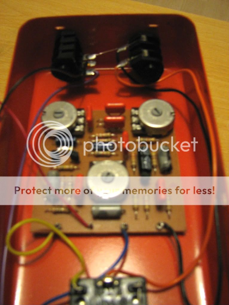
I built one of these for a friend using BC109s. Came out sounding pretty damn good, and before sending it to him I added a master volume out the side upon request.

he quoted "it's the best distortion I've ever had". I dont know if i'd go THAT far...but its a still a rad pedal.
he quoted "it's the best distortion I've ever had". I dont know if i'd go THAT far...but its a still a rad pedal.
I hope you'll find those pics useful as wellElectric Warrior wrote:I just fought myself through dozens of Power Boost and Overdriver gut shots. Here's some variations of the circuit:
http://www.megaupload.com/?d=S3OUCL39
-
Aharon
- Solder Soldier
Dr Tony Balls wrote:I built one of these for a friend using BC109s. Came out sounding pretty damn good, and before sending it to him I added a master volume out the side upon request.
he quoted "it's the best distortion I've ever had". I dont know if i'd go THAT far...but its a still a rad pedal.
Hey Dr Tony ,did you just stripboard it and which schem did you use...?
Thanks
Aharon
-
Dr Tony Balls
- Diode Debunker
yup!, used this vero layout, which checked out against the original schematic that you posted.
http://aronnelson.com/gallery/main.php/ ... d.jpg.html
http://aronnelson.com/gallery/main.php/ ... d.jpg.html
-
.Mike
- Solder Soldier
Information
I plan on building one of these. Out of curiosity, I modeled the three circuits with the gain up all the way to check out the difference in waveforms. In case anyone is interested, here are the results:

I'll probably do the frequency response later, and if anyone is interested, I'll post that if/when I get it done.

Mike

I'll probably do the frequency response later, and if anyone is interested, I'll post that if/when I get it done.
Mike
My website: America's Debate | My effects site: Just one more build...