I was picking up radio with the guitar volume all the way down before I pulled C5, so it wasn't doing it's job to begin with. I like that characteristic of Fuzz Faces anyways!
Any other component changes or just the C5?
How did you set the trim pots? I just went for 4.5v on the collector of Q2. I didn't really mess with the other one too much.
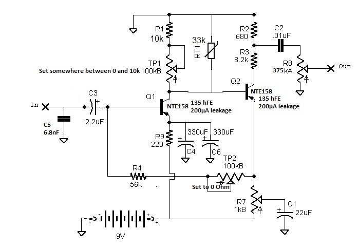
Dunlop - JD-F2 Fuzz Face, revision D [schematic]

I changed the input coupling cap from the original tantalum to a Mallory film cap, but I forget what size, probably the same 2.2 uF as the original cap. Most of the mods I've done are summed up earlier in this thread, I can't recall exactly what they were at the moment.
For the feedback-controlling trimpot, I try setting it to the maximum resistance (for minimum negative feedback - more fuzz!) which you'll get when the two legs that are shorted together by a trace on the board are also shorted by having the pot set all the way to the same side (thereby putting 100k between those legs and the third,) but I've found that I can't get anywhere near half the supply voltage on the collector of Q2 without dialing it back a bit, so I've been tweaking all three pots (including the one I added to replace the 8.2k on Q2's collector,) and monitoring the voltage. It will fluctuate pretty wildy, even with the thermistor RT1 which is supposed to mitigate temperature-related changes in transistor gain. Eventually, I will replace the Q2 collector trimpot with an external bias control, which I've found very useful in my silicone fuzz face. Maybe I'll just externalize all of the trimpots so I can tweak with ease. But that's just adding one more thing to my mountain of projects yet to be realized.
For the feedback-controlling trimpot, I try setting it to the maximum resistance (for minimum negative feedback - more fuzz!) which you'll get when the two legs that are shorted together by a trace on the board are also shorted by having the pot set all the way to the same side (thereby putting 100k between those legs and the third,) but I've found that I can't get anywhere near half the supply voltage on the collector of Q2 without dialing it back a bit, so I've been tweaking all three pots (including the one I added to replace the 8.2k on Q2's collector,) and monitoring the voltage. It will fluctuate pretty wildy, even with the thermistor RT1 which is supposed to mitigate temperature-related changes in transistor gain. Eventually, I will replace the Q2 collector trimpot with an external bias control, which I've found very useful in my silicone fuzz face. Maybe I'll just externalize all of the trimpots so I can tweak with ease. But that's just adding one more thing to my mountain of projects yet to be realized.
-
DrNomis

- Old Solderhand
Information
- Posts: 6807
- Joined: 16 Jul 2009, 04:56
- my favorite amplifier: Self-Built Valve Amp Head :)
- Completed builds: Dallas Arbiter Fuzz Face,Tone Bender Professional Mk 3,Tone Bender 3-Knob,Baja BK Butler Tube Driver,Baja Real Tube Overdrive,Roger Mayer Octavia,EH Soul Preacher,Tech 21 XXL Distortion,MFOS Weird Sound Generator.
- Location: Darwin,Northern Territory Australia
- Has thanked: 98 times
- Been thanked: 279 times
I noticed in the schematic of the Jim Dunlop Fuzz Face Reissue,that the emitter terminal of Q1 and Q2 aren't going the correct way,particularly Q2,which should be going straight to ground,if you were to build the circuit as-is on a breadboard,you would find that you will get very little gain out of it,i know from first-hand experience.... 
Genius is not all about 99% perspiration, and 1% inspiration - sometimes the solution is staring you right in the face.-Frequencycentral.
-
DrNomis
- Old Solderhand
Information
- Posts: 6807
- Joined: 16 Jul 2009, 04:56
- my favorite amplifier: Self-Built Valve Amp Head :)
- Completed builds: Dallas Arbiter Fuzz Face,Tone Bender Professional Mk 3,Tone Bender 3-Knob,Baja BK Butler Tube Driver,Baja Real Tube Overdrive,Roger Mayer Octavia,EH Soul Preacher,Tech 21 XXL Distortion,MFOS Weird Sound Generator.
- Location: Darwin,Northern Territory Australia
- Has thanked: 98 times
- Been thanked: 279 times
Just had another look at that schematic,it looks a bit bizarre to me,normally the 8k2 and the other series resistor should be connected to the collector for the transistor to provide current gain,here,Q2 is effectively operating as a common emitter amplifier,which can only produce a gain slightly less than one....
So,my conclusion is that transistors Q1 and Q2 are connected the wrong way around for a Ge PNP type Fuzz Face circuit...
So,my conclusion is that transistors Q1 and Q2 are connected the wrong way around for a Ge PNP type Fuzz Face circuit...
Genius is not all about 99% perspiration, and 1% inspiration - sometimes the solution is staring you right in the face.-Frequencycentral.
-
DrNomis
- Old Solderhand
Information
- Posts: 6807
- Joined: 16 Jul 2009, 04:56
- my favorite amplifier: Self-Built Valve Amp Head :)
- Completed builds: Dallas Arbiter Fuzz Face,Tone Bender Professional Mk 3,Tone Bender 3-Knob,Baja BK Butler Tube Driver,Baja Real Tube Overdrive,Roger Mayer Octavia,EH Soul Preacher,Tech 21 XXL Distortion,MFOS Weird Sound Generator.
- Location: Darwin,Northern Territory Australia
- Has thanked: 98 times
- Been thanked: 279 times
Yep,Q1 should have it's emitter going to R9 (the 330 ohm resistor),and Q2 should have it's emitter going to R7 (the 1k Fuzz pot)....
Genius is not all about 99% perspiration, and 1% inspiration - sometimes the solution is staring you right in the face.-Frequencycentral.
Yeah, after 2+ years, I just noticed that. My mistake in drawing the schematic. They should be the other way around. The transistors in the actual circuit are, I assure you, correctly oriented and sound lovely.
I'll see about updating the schematic to fix those and a few other minor errors/later changes, but being a busy college student, it might be a while. I've also got a great wah project on the mental workbench right now, so that is commanding much of my attention.
I'll see about updating the schematic to fix those and a few other minor errors/later changes, but being a busy college student, it might be a while. I've also got a great wah project on the mental workbench right now, so that is commanding much of my attention.
-
DrNomis
- Old Solderhand
Information
- Posts: 6807
- Joined: 16 Jul 2009, 04:56
- my favorite amplifier: Self-Built Valve Amp Head :)
- Completed builds: Dallas Arbiter Fuzz Face,Tone Bender Professional Mk 3,Tone Bender 3-Knob,Baja BK Butler Tube Driver,Baja Real Tube Overdrive,Roger Mayer Octavia,EH Soul Preacher,Tech 21 XXL Distortion,MFOS Weird Sound Generator.
- Location: Darwin,Northern Territory Australia
- Has thanked: 98 times
- Been thanked: 279 times
At least you know now mate...
Genius is not all about 99% perspiration, and 1% inspiration - sometimes the solution is staring you right in the face.-Frequencycentral.
-
jeepe

- Breadboard Brother
Information
- Posts: 73
- Joined: 10 Jun 2019, 16:48
- Completed builds: I might be at level 2, so to speak..
not totally green, but that's all :)
my "level" is about building a big muff... medium complexity :)
I'll never build a DS-2, for example :)
- -
even though I'm a layman to electronics
I'll never build anything without seeing the actual schematics too...
- -
my all time favorite: Fuzz FAce
it is an always ongoing project..
- -
I want to end up strumming some strings at the end of the day, whatever the sound
- -
I'm so sad that this beautiful culture (and freedom movement) is totally ephemeral - Location: Budaspest, Europe
- Has thanked: 625 times
- Been thanked: 22 times
hi, Guys,
just another time traveller here (from 2021)
the schematic of this thread as a picture, regardless of this conversation, is circulating all over the web as a J_D_F_2 schematic-- google's magic...
also, people's magic who'll just "feel lucky" and take what google gives them as a sure thing... regardless of the original context...
(syndrome: "confirmation bias" )
so, dear all who see this in the future:
FIY: the schematic at the beginning of this thread is faulty...
take a look at this thread instead:
viewtopic.php?f=1&p=283645#p283645
where they concluded in this ↓ ↓ schematic version:
in this post:
viewtopic.php?p=277952#p277952
.
.
good luck with your f* f*
just another time traveller here
the schematic of this thread as a picture, regardless of this conversation, is circulating all over the web as a J_D_F_2 schematic-- google's magic...
also, people's magic who'll just "feel lucky" and take what google gives them as a sure thing... regardless of the original context...
(syndrome: "confirmation bias"
so, dear all who see this in the future:
FIY: the schematic at the beginning of this thread is faulty...
take a look at this thread instead:
viewtopic.php?f=1&p=283645#p283645
where they concluded in this ↓ ↓ schematic version:
in this post:
viewtopic.php?p=277952#p277952
.
.
good luck with your f* f*
pedal building, tracing and sharing is such a beautiful freedom movement... If only it could be viewed as a future heritage, but it really is ephemeral, as it seems
-
george giblet

- Resistor Ronker
I have to admit the final schematic looks a bit weird to me. The connection of pot R7 to the battery looks wrong. It would make more sense going to the emitter of Q1/C4/C6. However when I trace the R7 connection on the PCB is look like the schematic is correct.where they concluded in this ↓ ↓ schematic version:
Going back to the pics in the thread:
- The red-wire is on pin 9 of the connector. That's 9V.
- That goes to the 220R on the PCB
- Then *after that* it goes to the emitter of Q1 and what looks like a track down to C4 and C6.
So that part of the schematic matches the PCB and it makes sense.
The connection from the dark blue from the pot R7 is the difficult one.
The dark blue wire goes to pin 3 on the connector. We can't see any tracks from pin 3 so we don't know where they go.
On the bottom side of the board there's no connections to pin 3 so the tracks must be on the top side.
The thing is I can't see an obvious tracks to Q1/C4/C6. And there's no track going to C4/C6 around outside of the PCB
to the top right corner of the board. So we can only assume the track from pin 3 goes along the top edge of the PCB to pin 9 (+9V).
That's how the schematic is drawn.
-
jeepe
- Breadboard Brother
Information
- Posts: 73
- Joined: 10 Jun 2019, 16:48
- Completed builds: I might be at level 2, so to speak..
not totally green, but that's all :)
my "level" is about building a big muff... medium complexity :)
I'll never build a DS-2, for example :)
- -
even though I'm a layman to electronics
I'll never build anything without seeing the actual schematics too...
- -
my all time favorite: Fuzz FAce
it is an always ongoing project..
- -
I want to end up strumming some strings at the end of the day, whatever the sound
- -
I'm so sad that this beautiful culture (and freedom movement) is totally ephemeral - Location: Budaspest, Europe
- Has thanked: 625 times
- Been thanked: 22 times
I agree...george giblet wrote: ↑16 May 2021, 23:58I have to admit the final schematic looks a bit weird to me.where they concluded in this ↓ ↓ schematic version:
although I can't make electric engineering considerations
I only use common sense reverse-reverse engineering...
see here at fuzz central:
https://fuzzcentral.ssguitar.com/fuzzface.php
or this at electrosmash:
https://www.electrosmash.com/fuzz-face
or R.G. Keen's analysis:
http://www.geofex.com/article_folders/f ... fffram.htm
what's "pot R7" here, always goes to the ground...
and C1 makes sense being a controllable / variable "bleed" along it...
in the schematic above, however, the 1k / R7 as a resistor doesn't go to where C1 goes....
- - -
even BJFE Björn's fuzz 109's schematic has an R7...
and the capacitor and pot and resistor combination, all in all, goes to ground, too... just like that R7...
https://moodysounds.com/wp-content/uplo ... -eng-1.pdf
- - -
PS:
nek123's schematic, as a matter of fact, is totally cool about this "R7 thing".... so maybe this is good and the other one is not...
so the good "warning" should go like either this or that is good, and the other one is faulty
pedal building, tracing and sharing is such a beautiful freedom movement... If only it could be viewed as a future heritage, but it really is ephemeral, as it seems
-
george giblet
- Resistor Ronker
The fuzz-central circuits are the classic circuits. I'm actually OK with C1 connecting to either supply rail. The C1 connection on JD-F2 valid from an electrical engineering point of view.and once again,
the fuzz central page is especially interesting cause there is a PNP GE version and an NPN SI version in one page, and
all the symmetries are clear
Adding a resistor to the emitter of Q1 like R9 on the Bjorn fuzz is OK too. The difference with R9 on the JD-F2 is there are big capacitors (C4, C6) on the emitter side. The big caps effectively remove R9 from the circuit. One view is is the big caps and R9 form a power filter but in that case you would expect R7 to connect to the emitter of Q1, after the supply filter. Another view is there's no supply filter as such, R7 connects back to the battery as usual, and R9 is bypassed by the big caps. The conclusion is R9 has been added to help stabilize the DC bias and the big caps are added to bypass R9 so it doesn't affect the tone or gain of the circuit.
So while the circuit looks a bit funny compared to the common circuits there is some sense to it. To the eye it just looks a little unconventional. If the circuit was drawn with a positive ground and the big caps were across R9 it would look a more normal (same goes for C1). The good thing is there's nothing wrong and the PCB looks like it follows the schematic.