Schematic:
Visual Sound - Pure tone buffer
-
Bernardduur

- Transistor Tuner
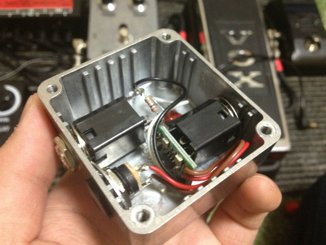
This was given to me as it does not function anymore. The IC is broken as there is a HUGE chunk taken out of it..... no idea why, I guess someone didn't take voltage ratings that close.
Schematic:
Schematic:
'No more....... loud music.......'
Follow my love for pedals and amps on https://bernardduur.blogspot.com and https://www.instagram.com/bernardduur1
Follow my love for pedals and amps on https://bernardduur.blogspot.com and https://www.instagram.com/bernardduur1
-
Bernardduur
- Transistor Tuner
Most capacitors are SMT and bear no markings. I have no capitance measuring device so I marked em a ?
'No more....... loud music.......'
Follow my love for pedals and amps on https://bernardduur.blogspot.com and https://www.instagram.com/bernardduur1
Follow my love for pedals and amps on https://bernardduur.blogspot.com and https://www.instagram.com/bernardduur1
-
Fredenando
- Breadboard Brother
This is an image from a japanese web for give us an idea...
-
IvIark
- Tube Twister
Information
Thanks for the schematic Bernard. I think we can assume C1 is 1n or less, if it's just to protect against RFI then you often see 100p in that position. C2 can be pretty much anything that won't start cutting low end in the filter and so 100n should do nicely. And the filter caps should be fine at 100u for C4, 47u for C5 as is commonly used. Or 47u for both. Or whatever, it's a buffer 
Oh and I've guessed at TL072, is that right?
Oh and I've guessed at TL072, is that right?
- Visual Sound Pure Tone Buffer.png (27.19 KiB) Viewed 3806 times
"If anyone is a 'genius' for putting jacks in such a pedal in the only spot where they could physically fit, then I assume I too am a genius for correctly inserting my legs into my pants this morning." - candletears7 - TGP
-
Bernardduur
- Transistor Tuner
Yep, that is the way the one here is mounted. The 1u is soldered on the output wire and is just floating around very close to the enclosure without any protection......
'No more....... loud music.......'
Follow my love for pedals and amps on https://bernardduur.blogspot.com and https://www.instagram.com/bernardduur1
Follow my love for pedals and amps on https://bernardduur.blogspot.com and https://www.instagram.com/bernardduur1
-
Bernardduur
- Transistor Tuner
Yes, I would've guessed C1 would be like 47p - 100p and C2 around 22n - 100n. C4 and C5 don't have a polarity marking on them and look the same size as C2 but do differ in color (C2 is white / silver, C4/5 are brown). No idea if these can be SMT ELCO's......IvIark wrote:Thanks for the schematic Bernard. I think we can assume C1 is 1n or less, if it's just to protect against RFI then you often see 100p in that position. C2 can be pretty much anything that won't start cutting low end in the filter and so 100n should do nicely. And the filter caps should be fine at 100u for C4, 47u for C5 as is commonly used. Or 47u for both. Or whatever, it's a buffer
Oh and I've guessed at TL072, is that right?
The IC is marked 072 so a TL072 would be close!
'No more....... loud music.......'
Follow my love for pedals and amps on https://bernardduur.blogspot.com and https://www.instagram.com/bernardduur1
Follow my love for pedals and amps on https://bernardduur.blogspot.com and https://www.instagram.com/bernardduur1
Has anyone built this yet? I made one using lvlark's vero layout (using his suggested cap values), but it just makes a faint distorted signal and a ticking sound. This buffer is supposed to be inside all Visual Sound pedals, right? I have a 10th anniversary Visual Volume I'd be happy to take pictures and measurements of if it would be helpful. I rather like whatever buffer is in the volume pedal and I unsuccessfully tried tracing out the circuit inside to extract the buffer portion.
-
mmolteratx
- Degoop Doctor
No need to use a 47µ cap for the bias filter. 470k resistors mean you could use something like 100n.IvIark wrote:Thanks for the schematic Bernard. I think we can assume C1 is 1n or less, if it's just to protect against RFI then you often see 100p in that position. C2 can be pretty much anything that won't start cutting low end in the filter and so 100n should do nicely. And the filter caps should be fine at 100u for C4, 47u for C5 as is commonly used. Or 47u for both. Or whatever, it's a buffer
Oh and I've guessed at TL072, is that right?