Redesign of the Rockman X100 Chorus/Doubler.
I see this part of the project like this:
A) Try to build Rockman LFO, VCO, BBD and filters
B) If parts are hard to find, obsolete, expensive, superseded; try to use newer parts
C) Do any redesign that is necessary to accommodate the new parts but get same final result. If we add controls, the original Rockman settings should be possible at some setting of the pots.
In our case, we found original BBD IC110 MN3007 not easily available / Expensive / too many fakes in the market.
So we found a new part that can do the same job. CARVIN decided to use BBD MN3207 and a clock made out of a CD4046, similar to the LICH KING circuit.
Now we begin the redesign.
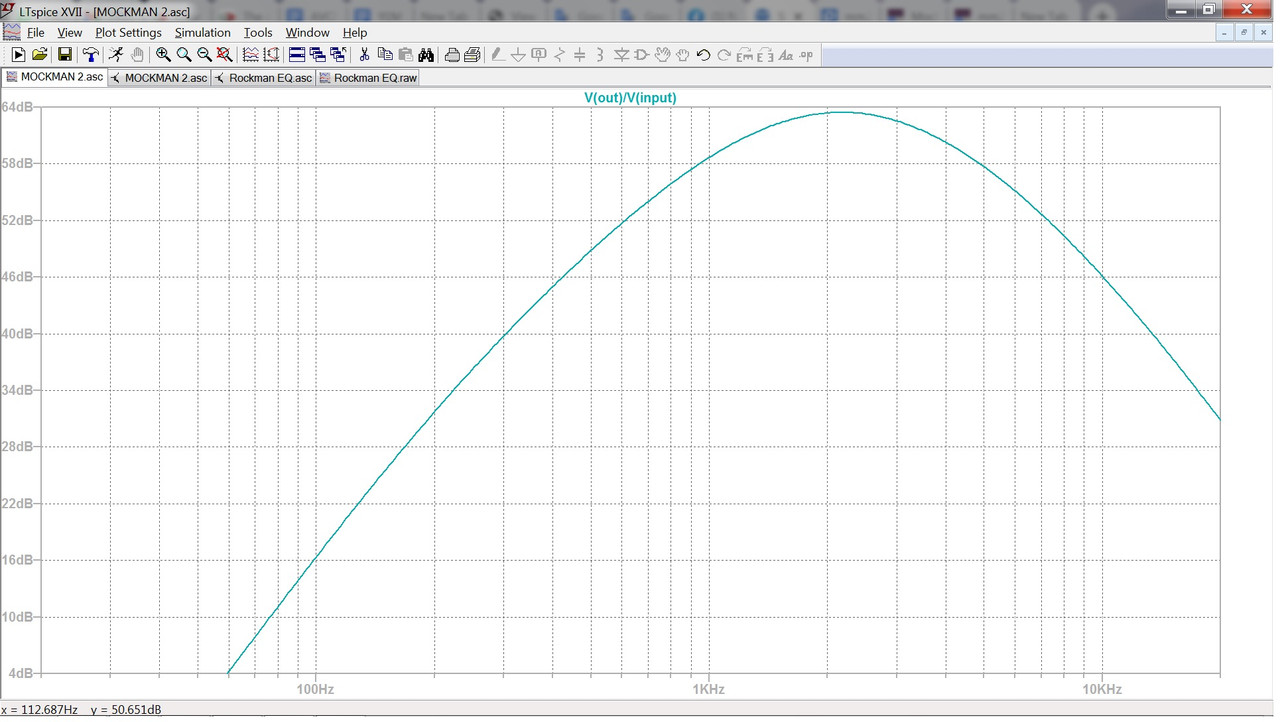
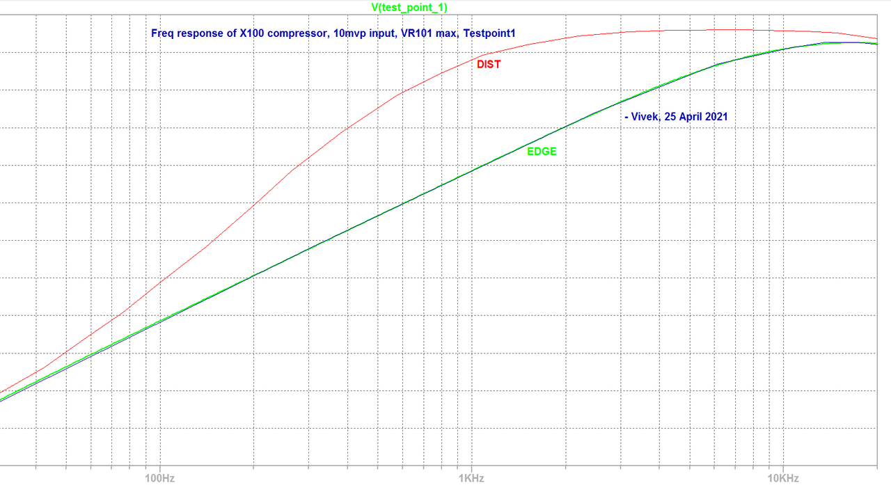
First step is to enter Rockman X100 LFO and VCO into SPICE to collect data. I found from SPICE analysis :
LFO speed fixed at 1.75 Hz
Base clock frequency 75Khz
Modulated 76-74 Khz by the LFO (needs to be triple checked since that appears to be too low modulation)
Now we have a target specification for the new design.
Then we try to redesign the Circuit to use MN3207 instead.
Oh Oh it can accept Power supply of 4 to 10 Volts
Earlier MN3007 could accept -15 Volts. Hence Tom ran it at +6 and -6 ie total of -12 volts on pin 5 as compared to pin 1
The MN3207 will blow at 12V supply, hence we need to redesign
Option A) Ignore the spec sheet and run it at 12V. Never too good an idea but such things have been done before
Option B) Get +4.5 and -4.5 volts somehow from the +/-6 V that we have for rest of the circuit. Added cost if we do it properly.
Option C) Feed it unipolar +6V which we do have anyway
CARVIN chose option C)
But now the LFO and VCO will also have to be unipolar so that the correct clock signals reach the MN3207.
We therefore need to do following design steps :
i) Redesign the LFO and VCO to use unipolar supply, and use CD4046 instead of 555, and make sure that the Rockman settings are available at some settings of the Pots.
Make sure that MN3207 has correct Vbias and Vdd bias voltages since they are different value and polarity than the MN3007.
ii) If rest of circuit was on Bipolar power, we need to DC uncouple the other parts from the BBD, VCO , LFO that will now have Unipolar power
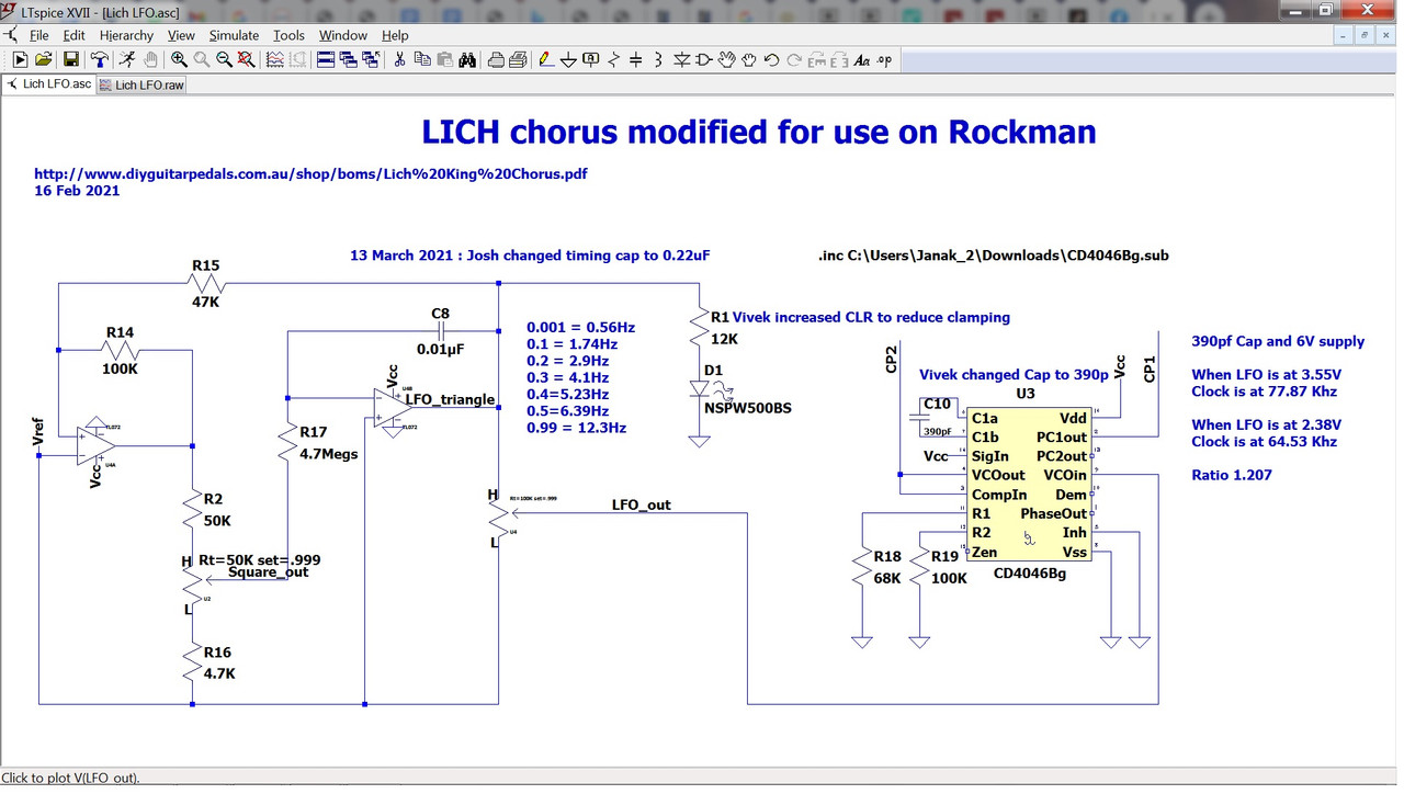
We get inspiration from the LICH KING schematic, but LICH has Unipolar voltage of 9V and different design specifications
So I entered LICH schematic into SPICE
It has variable LFO of 0.5 to 12 Hz and we see that 1.75 Hz is possible within the range of that LFO. Thats great, no change needed here.
I saw that it outputs 3 V plus minus 0.6V when Vs is 6 V
so now we need to check or redesign the LICH VCO so that it has same settings somewhere as the Rockman X100
At base control voltage, it should have same base clock as Rockman = 75 Khz
then at maximum swing, it has to have large frequency swing of 20% so that when we reduce the depth pot, we can reach Rockman estimate of 1 % modulation.
That's where we currently are in the design process.
Looking forward to your guidance, comments and corrections to above.
References :
A)
https://www.electrosmash.com/.../bucket-brigade-devices...
B)
https://electricdruid.net/.../MN3207-1024-Stage-Delay...
C)
http://www.diyguitarpedals.com.au/.../Lich%20King...
D) Rockman X100 Board 100 schematic by Pedro Yi
E)
https://www.ti.com/lit/an/scha002a/scha ... 3304808348