EHX - Big Muff Pi 1977 & 1978 version  [schematic]

All about modern commercial stompbox circuits from Electro Harmonix over MXR, Boss and Ibanez into the nineties.
User avatar
PokeyPete
Resistor Ronker
Information
Posts: 371
Joined: 31 Aug 2008, 01:45
Has thanked: 11 times
Been thanked: 43 times

Post by PokeyPete »

The Lifetaker wrote:Well I finally sat down and finished this pedal today. you can imagine my excitement when I hit the switch and the LCD actually turned on. Sadly, no sound came out. No buzz, no hum, nothing. I double checked and I'm pretty sure everything is wired correctly. I'm pretty sure there is something wrong with my veroboard job. I think I'll double check to make sure I have all the right parts, and just try again. :?


I'll get it someday. I'm getting close. :)
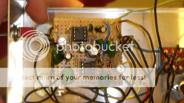
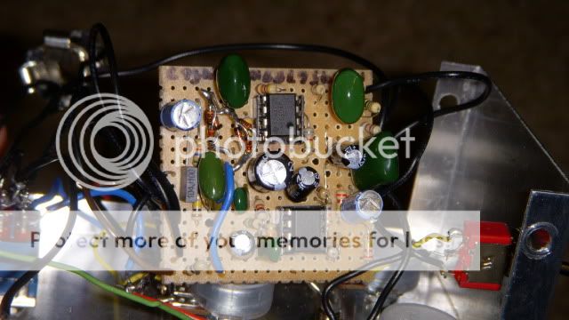
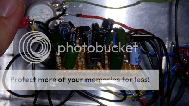
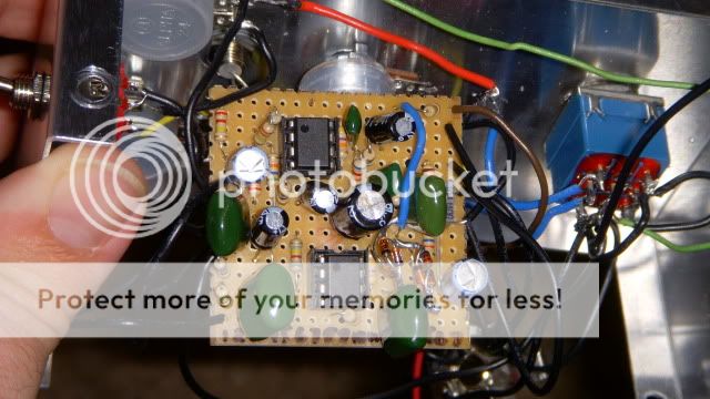
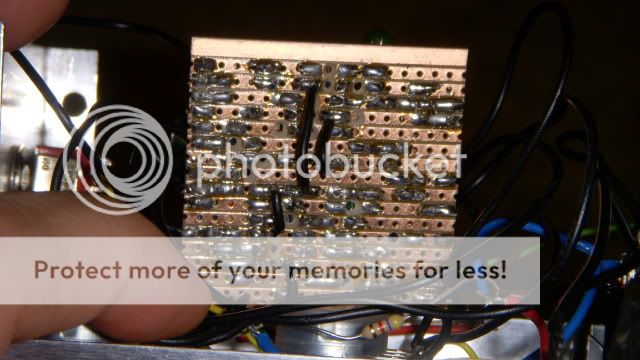
One thing that is not emphasized on the vero layouts is the off-board wiring schemes. It's possible that your vero board is
good, but you may have erred in the off-board wiring (input jack / switch / output jack). Listed below are a couple of sites
owned by forum members that market PCBs or complete projects. Check out their sites and look at several projects to see
how they route the guitar signal through the enclosure. Study the switch wiring to see what they are trying to accomplish.

http://www.madbeanpedals.com/projects/index.html

http://www.buildyourownclone.com/
“No man is so foolish but he may sometimes give another
good counsel, and no man so wise that he may not easily err
if he takes no other counsel than his own. He that is taught
only by himself has a fool for a master.”
–Hunter S. Thompson

User avatar
The Lifetaker
Information
Posts: 10
Joined: 04 Aug 2011, 19:29
Has thanked: 8 times
Been thanked: 1 time

Post by The Lifetaker »

Well for the wiring I just followed the true bypass diagram on Beavisaudio.com, so I'm pretty sure that's right.

However, I did some more research and then came home and took a look at my pedal, I'm gonna work on it for a few hours now that I know what I did wrong. 3 of my Electrolytic capacitors are in backwards, on top of that I put in film box type capacitors in the 1uF spots instead of electrolytic. I'm gonna run to my local store and grab the right capacitors and see if I can't pull the wrong ones and still salvage this pedal rather than start over.

Anyways, do you think such fatal errors would result in complete silence when I turn the pedal on? Or should it still be making some kind of noise?

Either way, I'll fix what I've found wrong with it and let you guys know! Thanks for all your help!

User avatar
The Lifetaker
Information
Posts: 10
Joined: 04 Aug 2011, 19:29
Has thanked: 8 times
Been thanked: 1 time

Post by The Lifetaker »

So I fixed everything and it didn't make a difference. When I turn the pedal on it goes silent. I tried to wire the foot switch a few different ways according to what I read online. Nothing. I give up. I'm just gonna have to find a friend who's better versed in electronics than myself.

For now, dinner, pizza, Star Wars, and a quiet Friday night at home.

User avatar
Seiche
Old Solderhand
Information
Posts: 2526
Joined: 01 Nov 2010, 00:16
Location: Germany
Has thanked: 231 times
Been thanked: 189 times

Post by Seiche »

The Lifetaker wrote:So I fixed everything and it didn't make a difference. When I turn the pedal on it goes silent. I tried to wire the foot switch a few different ways according to what I read online. Nothing. I give up. I'm just gonna have to find a friend who's better versed in electronics than myself.

For now, dinner, pizza, Star Wars, and a quiet Friday night at home.
it would definitely help if you'd post a few gut shots. that might make it obvious to some what you did wrong (and, understandably, couldn't see after hours of staring at it) :thumbsup

don't worry, we'll get this to work!

User avatar
The Lifetaker
Information
Posts: 10
Joined: 04 Aug 2011, 19:29
Has thanked: 8 times
Been thanked: 1 time

Post by The Lifetaker »

I appreciate that, man. I took a few shots of the vero board. Maybe you guys will be able to see if I'm doing something fundamentally wrong or using the wrong parts. I followed two different wiring diagrams, and got the same results both times:

First attempt:
Image

Second attempt:
Image

--no sound, so I'm thinking that there is just something wrong with the board. If you guys see anything let me know.

Image

Image

Image

Thanks, again!

User avatar
The Lifetaker
Information
Posts: 10
Joined: 04 Aug 2011, 19:29
Has thanked: 8 times
Been thanked: 1 time

Post by The Lifetaker »

Sorry about those pics, these one might be a little bit clearer:

Image

Image

Image

Image

Image

User avatar
The Lifetaker
Information
Posts: 10
Joined: 04 Aug 2011, 19:29
Has thanked: 8 times
Been thanked: 1 time

Post by The Lifetaker »

I followed Mike's layout:

Image

User avatar
mysticwhiskey
Solder Soldier
Information
Posts: 227
Joined: 03 Jul 2010, 09:55
Location: Adelaide, Australia
Has thanked: 42 times
Been thanked: 175 times

Post by mysticwhiskey »

This probably doesn't explain why you're not getting any sound, but you've wired the diodes incorrectly. Each lot of 3 need to be wired in series - you've got them wired in parallel.

User avatar
mysticwhiskey
Solder Soldier
Information
Posts: 227
Joined: 03 Jul 2010, 09:55
Location: Adelaide, Australia
Has thanked: 42 times
Been thanked: 175 times

Post by mysticwhiskey »

Not trying to be mean here, but your soldering looks untidy: there looks like there could be several potential short-circuits with the uninsulated connections between wires (eg the LED resistor and the 9V wire), and especially those wires coming off the pots - looks like they could potentially be grounding out on the enclosure. And those jumpers on the backside of the board could be shorting out, but it's pretty hard to see what's going on in those pictures.

Definitely check for solder bridges between the vero rows too, there's a couple of spots that look like they could be touching, but then again it could just be the picture.

User avatar
Seiche
Old Solderhand
Information
Posts: 2526
Joined: 01 Nov 2010, 00:16
Location: Germany
Has thanked: 231 times
Been thanked: 189 times

Post by Seiche »

mysticwhiskey wrote:Definitely check for solder bridges between the vero rows
all of the above but especially this. check the trace cuts you made, because they tend to have microscopic traces bridging the gaps (one of the most likely faults in my builds). Try to use bright light source (sun light works best) and a magnifying glass (if you have one) when doing that.

User avatar
The Lifetaker
Information
Posts: 10
Joined: 04 Aug 2011, 19:29
Has thanked: 8 times
Been thanked: 1 time

Post by The Lifetaker »

Maybe I'm just not cut out for this stomp box gig.

Maybe I just need to move on.

Maybe there is something else out there for me... something... more.

Image

I'm kidding guys. I need to get a hold of a magnifying glass and check this shotty soldering job. I'm sure I'll find it, and thanks for pointing out the diodes being wrong! Now that I know I've got the write parts and can fix those diodes, I'll make a careful pass over the back and make sure nothing is touching. Should I be ok if I follow that first wiring diagram from beavis audio?

Thanks again for your responses, guys. Also, how thick should the solder I'm using be? What will give me the quickest cleanest results?

User avatar
The Lifetaker
Information
Posts: 10
Joined: 04 Aug 2011, 19:29
Has thanked: 8 times
Been thanked: 1 time

Post by The Lifetaker »

I found this:

http://www.guitarpcb.com/apps/webstore/ ... ow/2420040

It's only 10 bucks. I think I'm just gonna buy it and give this project another shot. I'll find a simpler verboard project, before trying this one again.

User avatar
johnnyg
Resistor Ronker
Information
Posts: 418
Joined: 31 Oct 2009, 16:57
Has thanked: 92 times
Been thanked: 43 times

Post by johnnyg »

The Lifetaker wrote:I found this:

http://www.guitarpcb.com/apps/webstore/ ... ow/2420040

It's only 10 bucks. I think I'm just gonna buy it and give this project another shot. I'll find a simpler verboard project, before trying this one again.
Yeah - don't give up and go with the pcb, it'll be easier for you (but I'm a bit biased - I don't like vero at all... I think it's junky and reminds me of the crappy flashing LED circuits etc I had to make in school). You may be able to reuse a lot of the parts on your vero for the pcb, but you'd probably have to reorder most of them (resistors and caps) as well just in case you've cut their leads too short for the pcb.

Solder: 22 swg / 0.7mm or thereabouts I use.

To simplify the off-board wiring, if you plan to run the pedal off a 9v PSU then I'd forget the battery snip (and use the simple, cheaper form of dc jack - not the switching type). I'd also ditch the LED - the original didn't have one I don't think. With no LED you can use better footswitches than the blue types - like the nice Carling ones. But that's just my personal preference - the whole point of this building malarkey is to build things the way you want them :thumbsup
Yet to break through the Space Charge

User avatar
Seiche
Old Solderhand
Information
Posts: 2526
Joined: 01 Nov 2010, 00:16
Location: Germany
Has thanked: 231 times
Been thanked: 189 times

Post by Seiche »

i agree, vero can be a real bitch. definitely not easy for starting out. i would recommend a booster or a fuzz face on perf for that.

User avatar
Gila_Crisis
Resistor Ronker
Information
Posts: 404
Joined: 01 Jul 2007, 08:37
Has thanked: 3 times
Been thanked: 124 times
Contact:

Post by Gila_Crisis »

here you'll find also my vero layout for the ICBM.
it's verified and full working.
Attachments
BigMuffOpamp1978ToneBypass.gif
BigMuffOpamp1977.gif
Zwischen Ordnung und Chaos fangt die Musik an

User avatar
IvIark
Tube Twister
Information
Posts: 2235
Joined: 01 Jan 2008, 23:59
Location: Manchester UK
Has thanked: 562 times
Been thanked: 586 times
Contact:

Post by IvIark »

I put together an alternative vero layout using a quad opamp for the OP77 and 78. To keep the width down so the boards will fit comfortably in a 1590b, I haven't laid the diodes out on the board and so D1 and D4 are 3 x 1N4148's in series. They're small enough to allow you to make these groups of 3 up yourself (and maybe cover them with shrink tubing) without looking unweildy on the board, so I thought it made the most sense to keep the layout as compact as possible. Currently unverified.

Image

Image
"If anyone is a 'genius' for putting jacks in such a pedal in the only spot where they could physically fit, then I assume I too am a genius for correctly inserting my legs into my pants this morning." - candletears7 - TGP

User avatar
monkeyxx
Resistor Ronker
Information
Posts: 279
Joined: 12 Jan 2011, 06:54
Has thanked: 52 times
Been thanked: 51 times

Post by monkeyxx »

I just have to post this picture, I updated the knobs and settled on the final version of my muff. I think they're reminiscent of the triangle and ram's head knobs. This is a really bright cutting distortion/fuzz compared to fuzz faces or shredmasters or whatever. very scooped.

https://i102.photobucket.com/albums/m11 ... pie006.jpg

User avatar
monkeyxx
Resistor Ronker
Information
Posts: 279
Joined: 12 Jan 2011, 06:54
Has thanked: 52 times
Been thanked: 51 times

Post by monkeyxx »

Image

User avatar
Bernardduur
Transistor Tuner
Information
Posts: 1219
Joined: 24 Aug 2007, 07:36
my favorite amplifier: Welagen - ODR
Location: Losser.........
Has thanked: 94 times
Been thanked: 735 times

Post by Bernardduur »

Just got one of these beauties from a friend; he was throwing it out and he asked if I was interesed......

Indeed I was :)

It was modded quite heavily through the years. My friend does not know who did the mod but he had it this way all his life. It did only function half......... he never really cared for it.

The mod was a different output for the 'booster' function that made the gain unity when the booster was switched 'off'. Works quite nice but the difference between the gain pot (sustain) and the mod was not noticeable. I removed the booster switch. The two (??) switches on the back switched germanium diodes parallel to the silicium diodes...... really small effect!
EHX - Muff mod.JPG
I now use one switch to bypass the tone controls. The other mod is my 'bass' mod which puts a 1.8nF cap parallel to the 150pf cap on the uA741. It cuts the annoying highs perfectly!
'No more....... loud music.......'
Follow my love for pedals and amps on https://bernardduur.blogspot.com and https://www.instagram.com/bernardduur1

User avatar
fuzzguy
Information
Posts: 18
Joined: 14 Oct 2012, 17:42
Location: The Netherlands
Has thanked: 3 times
Been thanked: 1 time

Post by fuzzguy »

I was researching this thread because I want to build an opamp muff. Great thread! First I thought about buying the pcb from guitarpcb.com, but I think I'll choose one of the vero's from this thread, probably the '78 with tone bypass Monkeyxx made (based on the one by gila crisis). Because this one doesn't have the "sustain mod" that some people commented it sounds better without.

I want to socket the tone-stack components to be able to change them if I want more mids/etc.
In monkeyxx '78 layout, r15 is the one you can replace with a pot I think? (keep the 1k2 and put a 25 k pot in series?).
I think r15, r14, c10 and c12 are the tone-stack ones, right?

One thing, the layout says "watch cut under r17" surely there's not supposed to be a cut there, it would be blocking sustain2?

Image

Post Reply