Hi.
I just did this conversion. For me there are some aspects missing in Asil's picture (post #13
viewtopic.php?p=153306#p153306).
My NF-1 was an earlier version than the ones I could find a Service Manual to, it's a little bit different.
The PCB looked like this :
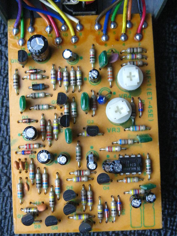
Main differences, among others, which make it closer to an SG-A by the way (according to the service manual I could find anyway) :
- the led driving transistor Q10 on the top left corner
- the first resistor to half-voltage (left of Q1, see service manual) was already 470k
- the 33n cap come before the 1M resistor between Q3 and Q2
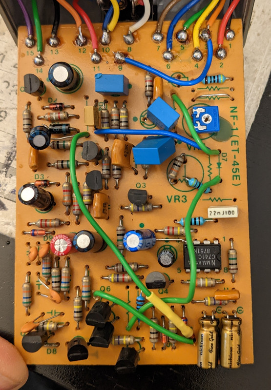
Here's how my successfully modded NF-1 looks now. I had to drill holes, make some bigger to fit several components leads inside, cut or link or reuse traces, etc. O also took the opportunity to replace all electrolytic caps and change them to film caps when in the signal path, and to get rid of the PCA/ACA 12V/9V diode and resistor.
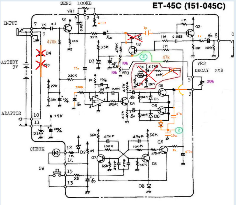
In order to help others, I corrected Asil's modified NF-A schematic, here's what I added / modified (if I still manage to remember all of them well !) :
- wrong components values
- two 1µ in series between Q1 and Q2, direct connection to Q3 in between them
- pin 2 of the IC going to resistor (390r not 680) and 1µ cap to ground, not to half-voltage
- clarified and corrected the whole Q5/Q6/diode added part of the circuit mayhem
- clarified what was connected to the Decay (attack) pot.
Just to be clear : I didn't take the time to understand how the circuit works, I don't know if all the changes I added are necessary (I do now that if pin 2 goes 680r and 1µ then to half-voltage rather than ground that doesn't work, though, since I hadn't seen that difference between the two circuits at first). What I do know is that now I have SG-1 copy that sounds how it should, even if it wasn't easy

There you go :
Have a great day everyone !

