Original effects with schematics, layouts and instructions, freely contributed by members or found in publications. Cannot be used for commercial purposes without the consent of the owners of the copyright.
This is my first effort at a vero layout
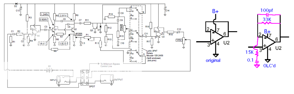
Its based on the OLC variant, which was based on the Big Cheese.
Would appreciate someone taking a look over it, or if you fancy building it.
When I wanted to do a cheese there was no vero's available and I'm sure it could be done better but noone has in many years, so it is what it is for now.
There was a company called OLC (officially licensed circuits) who made a pedal called the Chunky Cheese (as a kit, and as a prebuilt device).
I copied their build documents.
This is their build guide... http://www.olcircuits.com/documents2008 ... dguide.pdf
i guess there is a trace cut under R3.
Check the connections of C5 and also D1 and have a good look at the connections of Q3 and what it connects to. Thats as far as i have got. You need to fix those mistakes before i can go on.
yep i know all about it. IC2 pin 4 should go direclty to ground. R17 can go to ground at the top of the board and that will save a line. After those couple of fixes your there.
I havn't looked at that yet, but here is an idea you may want to consider. To make the layout fit an a box easier i do big layouts like this. And yes i know what you are going to say. Ive done plenty of layout and then had to do them over again don't worry. Anyway, in this diagram the signal follows the arrows. I try to stick to 30 holes across because it fits the boxes i use just nice. And i can go about 20 something holes the other way and still have plenty of room for switches and jacks and battery. Hope it helps a bit, well maybe for next time.
Ok I think I have address your changes. R3 was completely off, but now sorted. I think everything around Q3 is sorted, not sure about the jumper between C and E though...
Thanks so much for your time and help thus far..ill repost when I have had time to properly review, rather than look even more foolish (!)
Last edited by LaceSensor on 20 Jul 2011, 17:56, edited 1 time in total.
I hear what you are saying about better layouts but this was my first EVER, so its a steep learning curve.
If I can get this one correct it will be a basis for revisions later.
Damn i just saw C16 needs to be grounded too, and id removed teh connection from pin 2 IC2 to R20 ..sigh! LOL
I have a new found respect for ppl doing layouts
I'll check the layout in the morning for you pal its 3.50 am here. I need some sleep.
LaceSensor wrote:I hear what you are saying about better layouts but this was my first EVER, so its a steep learning curve.
If I can get this one correct it will be a basis for revisions later.
Your doing ok. It's pretty tricky isn't it. I know it's your first (might be your last) I'm just trying to stick some ideas in your head. I get pretty stupid with my layouts. I have trace cuts every where so the signal doesn't travel down tracks for no reason. It ends up more like a pcb.
Shit dude, get some sleep! thanks so much
I think its done. I keep rechecking it over and over.
I will take the time to make this vero, even though I just made the OLC on perf...ive got a mate who would likely take the vero off my hands
Ill be back with what I beleive is a final version for you to look at, at your leisure