
Even though it's such a simple circuit, which can be easily done on vero or perf I made a pcb layout for it. I'll see if I can make a complete project out of it (as a pdf).
Helge
Fred Briggs - E11even - Marshall Boost/OD
-
briggs

- Tube Twister
Information
HEAD wrote:Even though it's such a simple circuit, which can be easily done on vero or perf I made a pcb layout for it. I'll see if I can make a complete project out of it (as a pdf).
Helge
Because I'm a knobSeiche wrote:you're right, that's true. I didn't look at the labeling and assumed "gain" would be "bias"Ben N wrote:Take another look, Seiche. What is labeled "Bias" on the schematic is really the clipping control, not transistor bias.
FRED Y U LABEL CLIPPING HEADROOM "BIAS"?

I am Klon.
-
geiristudio

- Breadboard Brother
Damn, I just finished putting a circuit together and finding that I'm all out of BS170's. I have a bunch of transistors, is there anyone that I could use instead and get the same results?
-
mictester

- Old Solderhand
Information
No. You can use a 2N7000 as a close equivalent, but remember the BS170 is a FET, not an ordinary transistor.
Buy a bag of them - you can use them for boosters, buffers, fuzzes, and even "Millennium Bypass" LED indicators!
Buy a bag of them - you can use them for boosters, buffers, fuzzes, and even "Millennium Bypass" LED indicators!
"Why is it humming?" "Because it doesn't know the words!"
-
briggs
- Tube Twister
Information
The BS170 is one of my "most used" semi-conductors - I like to have a lot of them around. I'd even say they would probably come mid-table in my "top 10 best friends" listmictester wrote:No. You can use a 2N7000 as a close equivalent, but remember the BS170 is a FET, not an ordinary transistor.
Buy a bag of them - you can use them for boosters, buffers, fuzzes, and even "Millennium Bypass" LED indicators!
I am Klon.


-
geiristudio
- Breadboard Brother
Hah I managed to find one from a broken circuit I had lying around. So I build the vero but I'm not getting it to work. I've traced it a few times now and I'm positive that everything is connected properly. The board is very clean and nothing is touching. Has anyone verified the vero? It's pretty small so it shouldn't be hard to do it right in the first place 
-
rizibiz

- Breadboard Brother
Okay, I re-checked my layout twice again. I don't see any errors in comparison to the schematic.geiristudio wrote:Hah I managed to find one from a broken circuit I had lying around. So I build the vero but I'm not getting it to work. I've traced it a few times now and I'm positive that everything is connected properly. The board is very clean and nothing is touching. Has anyone verified the vero? It's pretty small so it shouldn't be hard to do it right in the first place
Do you have all the trace cuts?
under the 10K resistor (coordinates: C1)
under 100nF cap (I1)
and at G2?
BS170 orientation? Could the scavenged part be damaged?
Zener orientation? Cathode faces towards MOSFET Gate.
-
geiristudio
- Breadboard Brother
Thanks for the reply. The cuts are fine and orientation of the BS170, not 100% sure if they're damaged but I don't think so. I'll check that. I took the orientation of the Zener that the line on the diode is the same as the black line on the layout, right?
I'm gonna have a closer look at everything soon when I get to it and I'll report what I find.
Cheers!
I'm gonna have a closer look at everything soon when I get to it and I'll report what I find.
Cheers!
-
rizibiz
- Breadboard Brother
Well, ok, this might be my bad. I used too small size for the diode symbol on the layout. Should have used larger where the two colors are not covering equal areas.
White denotes the cathode of the diode in the layout. I think all diodes have the cathode marked.
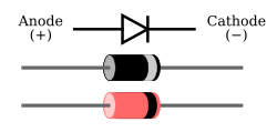
So you should reverse the zener.
On those orangish Zeners the black ring is cathode.
White denotes the cathode of the diode in the layout. I think all diodes have the cathode marked.
So you should reverse the zener.
On those orangish Zeners the black ring is cathode.
-
geiristudio
- Breadboard Brother
Cheers for that man! I just misunderstood the layout. I have the diodes the other way around so I'm gonna flip them and see if that helps.
-
geiristudio
- Breadboard Brother
Yeah the two Bat41 are okay but I had the other diode the wrong way so I flipped that and the pedal works.
Fred, I gotta tell you. This circuit sounds amazing! I've bee playing with both my 1987 Fender Strat Plus and My les Paul thorugh a 1984 JCM800 2204 and it rocks!
Here's how the pedal looks like:

Fred, I gotta tell you. This circuit sounds amazing! I've bee playing with both my 1987 Fender Strat Plus and My les Paul thorugh a 1984 JCM800 2204 and it rocks!
Here's how the pedal looks like:
-
briggs
- Tube Twister
Information
Really glad you like it. It gives your tone a sort of presence even when it's turned down low - just a sort of brilliance and shimmer that wasn't there before. When you combine it with the other "Vintage" boosters I designed you can get some really rocking sounds out of them. I like running the 'Face into the E11even with them both on a medium gain setting but with the Body control on the E11even set quite high to give you the classic Marshall 470k/470pF mid filtergeiristudio wrote:Yeah the two Bat41 are okay but I had the other diode the wrong way so I flipped that and the pedal works.
Fred, I gotta tell you. This circuit sounds amazing! I've bee playing with both my 1987 Fender Strat Plus and My les Paul thorugh a 1984 JCM800 2204 and it rocks!
Here's how the pedal looks like:
I am Klon.
-
geiristudio
- Breadboard Brother
Cool, I'm also gonna try the 'Face circuit and see how I like it. I'm pretty sure I'll like it!
Oh and by the way, the pots on the vero layout are reversed. I need to turn everything back to turn things up. I don't mind because I'm keeping this for myself.
What does the "Bias" knob do, in terms of sound? I can't really hear anything happening when I turn it. I'm sure that I wired it correctly though. Well, maybe it doesn't work because of the reverse pinouts of the pots ?
-
briggs
- Tube Twister
Information
I think the 'Face is my overall favourite of the three. The "Bias" control is just a saturation control for the diodes, increasing the resistance between the signal and the diodes should create a more dynamic, less clipped tone...
I am Klon.
-
geiristudio
- Breadboard Brother
Alright, thanks! Could you check the vero layout and see if the pots are wired correctly? I can't hear a difference when turning the bias knob at all.
-
briggs
- Tube Twister
Information
Yeah, the vero looks correct to me. Here's a tip - if you are already playing the amp with a fair amount of gain you may not hear the transistion. If you turn your amp to completely clean and then engage to boost (set it to max gain) then play with the bias knob. As you lower the headroom you'll hear the clipping starting to come in..
I am Klon.