A few years back I was playing around with cabsims for direct recording to a mixer or soundcard with no guitar amplifier. Most all the designs I tried including the Marshall SE100 and the infamous LXH2 designs left a lot to be desired - they all use lots of op amp filters that ended up making the guitar sound flat and lifeless in my opinion. These days cheap dsp has meant impulse response based designs work a lot better, but you should know me by now - I like to do things a little differently. Sometimes they work - sometimes they end up stashed away in a dark corner of the workshop
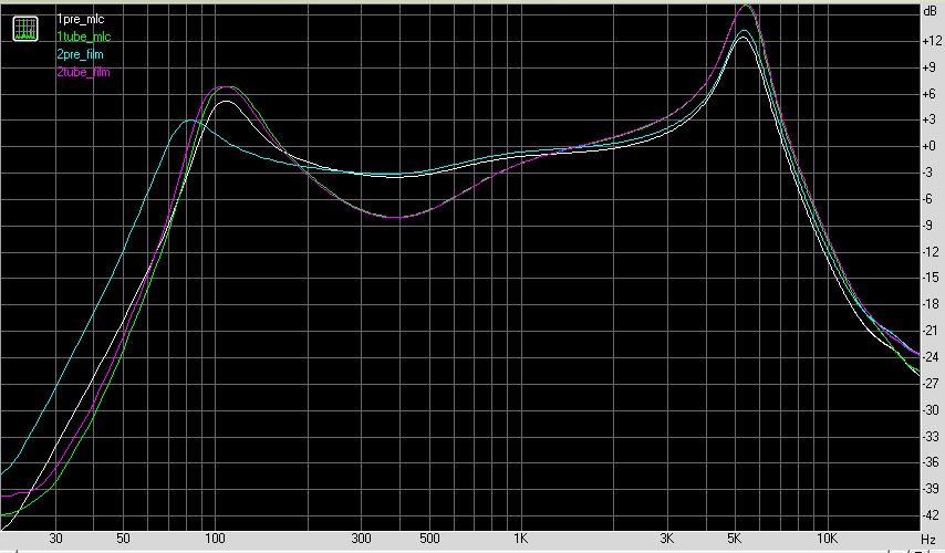
Anyway being a diy kinda guy and for something to do, I revisited an older design of mine in the hopes of improving it and creating a working pedal - here is the result of my efforts, a speaker cabinet simulator based on the response characteristics of the Marshall 1960A quad box loaded with Celestion vintage 30 loudspeakers. In addition I have included the response characteristic of a typical tube output stage, output transformer reactive loading stage with the cabinet response - this can be switched in or out for comparison
Please note: THIS IS NOT A LOAD BOX FOR USE WITH THE OUTPUT OF A VACUUM TUBE OR HIGH POWER SOLID STATE AMPLIFIER
This pedal is designed to be used as the final link before a mixer or soundcard with NO POWER AMPLIFICATION required
I have included a balanced XLR DI output and a switchable true bypass unbalanced jack output. The jack output has a level control.
Anyway here it is:
enjoy
bajaman