Fred Briggs - Hummingbird Overdrive *FINAL*
-
hbo

- Breadboard Brother
Information
A kind soul already verified my vero layout as working, so that one's good to go. Only thing I'm uncertain about is the orientation of some of the pots.
-
azrael

- Cap Cooler
o dang. i thought 47n looked a little odd, seemed like a rather large amount of high to roll off, that's why I assumed it was a resistor. Like maybe it was to knock off some signal before it went into the final gain stage.briggs wrote:azrael wrote:^There's a part at the right side of the schematic, it's a capacitor symbol, but it's given the value 47k? I redrew it as a resistor, R9 in my schematic.
I redrew the schematic in Eagle, and made a single sided PCB layout with board mounted pots. I used some different transistors just for pinout and layout model purposes.
If the redrawn schematic checks out, and if people are interested of course, I can post the files needed for the layout.
Any comments on how the layout could be better are welcome, of course.Ah, so many little errors in my schematic. That is a capacitor as far as I can remember (47n value), I'll check and confirm. The layout looks good! Anyone knocked this up yet? I like it with either a low gain PNP Ge transistor or a real high gain silicon pnp transistor (in the final stage of the discrete opamp)....
The vero looks good too, I need to restock myself with some of that stuff!
I have not built it yet, but I did print the PCB transfers. So soon!
It would be a simple thing to change, of course.
-
briggs

- Tube Twister
Information
ahhh, sorry azrael I haven't opened it up yet. I'll do it next time I'm with the unitazrael wrote:So was the part in question a cap or resistor?

I am Klon.
-
briggs
- Tube Twister
Information
It's a 47n cap 
I am Klon.
-
hbo
- Breadboard Brother
Information
Finally got around to building this one last night (from my previously posted vero) and I'm absolutely positively happy with how it sounds. May end up keeping the "compression" pot fixed, but the "shimmer" one deserves to be panel mounted.
Thanks a lot for this one, Briggs!
Thanks a lot for this one, Briggs!
-
briggs
- Tube Twister
Information
Cheeers Harald! I'm really glad you like ithbo wrote:Finally got around to building this one last night (from my previously posted vero) and I'm absolutely positively happy with how it sounds. May end up keeping the "compression" pot fixed, but the "shimmer" one deserves to be panel mounted.
Thanks a lot for this one, Briggs!
I am Klon.
-
DaveKerr

- Solder Soldier
Information
- Posts: 197
- Joined: 14 Mar 2010, 05:00
- my favorite amplifier: Ampeg M-15
Dynacord Preference 500 - Completed builds: Fuzz Face (2)
Tonebender MKII (3)
ROG Tri-Vibe
PAiA Ring Mod kit
Ring Mod based on Tim E schematic (2)
Rangemaster
CNO
ROG Splitter-Blender
Clari (Not) cubed deluxe - Location: Boston MA area
- Has thanked: 53 times
- Been thanked: 10 times
I'd appreciate the project files if it's not too much trouble, I've put away my etching tray and have been sending stuff directly off to Dorkbot post breadboardazrael wrote: I redrew the schematic in Eagle, and made a single sided PCB layout with board mounted pots. I used some different transistors just for pinout and layout model purposes.
If the redrawn schematic checks out, and if people are interested of course, I can post the files needed for the layout.
... multiple LFO waveforms (saw up, saw down, triangle, square); a more flexible envelope with attack/release controls as well as inverted envelope. I am afraid it will have more knobs than the TGP annual convention - frequencycentral
-
azrael
- Cap Cooler
Just the schematic file, and taking a whack at a double sided layout?
Or gonna send a single sided layout to Dorkbot?
It's kind of a big PCB to send to dorkbot, considering how it costs more for a bigger board, that's why I ask.
Or gonna send a single sided layout to Dorkbot?
It's kind of a big PCB to send to dorkbot, considering how it costs more for a bigger board, that's why I ask.
-
DaveKerr
- Solder Soldier
Information
- Posts: 197
- Joined: 14 Mar 2010, 05:00
- my favorite amplifier: Ampeg M-15
Dynacord Preference 500 - Completed builds: Fuzz Face (2)
Tonebender MKII (3)
ROG Tri-Vibe
PAiA Ring Mod kit
Ring Mod based on Tim E schematic (2)
Rangemaster
CNO
ROG Splitter-Blender
Clari (Not) cubed deluxe - Location: Boston MA area
- Has thanked: 53 times
- Been thanked: 10 times
The schematic would be great, I'd take a stab at a 2 sided layout. Although given all the stuff I'd like to make, it'd probably be months before I get to it.
... multiple LFO waveforms (saw up, saw down, triangle, square); a more flexible envelope with attack/release controls as well as inverted envelope. I am afraid it will have more knobs than the TGP annual convention - frequencycentral

-
aion

- Solder Soldier
Information
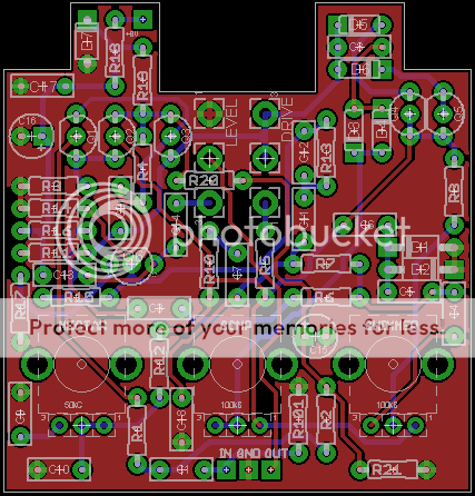
Long time lurker, but I finally have something to contribute! 1590B size, board mounted pots, power supply on the top instead of the side - my ideal layout. Not verified yet since I just finished it an hour ago, but I thought I'd post it and see if anyone would be interested in the Eagle files.
A couple of notes:
- The three pots on the bottom row are Alpha RV09AF-40's: 9mm pots, plastic shaft w/ indicator. I lifted this from the Subdecay Flying Tomato. Seemed like a great way to fit a lot of knobs into a 1590b, especially ones that won't be constantly twiddled like Drive and Level. The downside is that it may be a little too exact for some. (...although you could always offboard-wire those three if you wanted to use regular 16mm pots for all five)
- The transistor pinouts are based on azrael's Eagle schematic posted earlier - 2n3819's for Q1/Q2 and a 2N3906 for Q3.
- I drew the package for the 9mm pots based on the technical drawings in the datasheet, but I don't have any on hand to verify that everything measures out in real life.
- Alpha does not make RV09AF-40's in reverse audio, so the Nectar pot (50kC) will need some special treatment. Fred, not sure if you can offer any insight, but my first inclination is just to use regular audio taper since this is what the Honey Bee and the Timmy both use in their counterparts to this part of the circuit (though the Timmy wires it backwards). Another option would be to include some pads for extra tapering resistors, so a 100kB pot can be used with a 5.6k and a 450k resistor to approximate a 50k reverse audio. I'd gladly hear any feedback on this from those more experienced than myself.
Right now, the my next step is to make a Mouser order to verify that the 9mm pots have the right hole placement, and then send it off to Dorkbot. It'll still be a couple of weeks away, but if anyone is interested, I may end up with two spare boards if all goes well.
I'll post the Eagle files maybe tomorrow, along with a 1590B drilling template since everything is board mounted and needs to be exact.
-
briggs
- Tube Twister
Information
Wow, nice PCB layout. It'll be fine using a audio taper pot for the Nectar control. I'm tempted to revisit this design and have another tweak to it but I like the way it sounds. I still use my original build of this in my rig - it's on pretty much all the time as a low gain boost...aionios wrote:
Long time lurker, but I finally have something to contribute! 1590B size, board mounted pots, power supply on the top instead of the side - my ideal layout. Not verified yet since I just finished it an hour ago, but I thought I'd post it and see if anyone would be interested in the Eagle files.
A couple of notes:
- The three pots on the bottom row are Alpha RV09AF-40's: 9mm pots, plastic shaft w/ indicator. I lifted this from the Subdecay Flying Tomato. Seemed like a great way to fit a lot of knobs into a 1590b, especially ones that won't be constantly twiddled like Drive and Level. The downside is that it may be a little too exact for some. (...although you could always offboard-wire those three if you wanted to use regular 16mm pots for all five)
- The transistor pinouts are based on azrael's Eagle schematic posted earlier - 2n3819's for Q1/Q2 and a 2N3906 for Q3.
- I drew the package for the 9mm pots based on the technical drawings in the datasheet, but I don't have any on hand to verify that everything measures out in real life.
- Alpha does not make RV09AF-40's in reverse audio, so the Nectar pot (50kC) will need some special treatment. Fred, not sure if you can offer any insight, but my first inclination is just to use regular audio taper since this is what the Honey Bee and the Timmy both use in their counterparts to this part of the circuit (though the Timmy wires it backwards). Another option would be to include some pads for extra tapering resistors, so a 100kB pot can be used with a 5.6k and a 450k resistor to approximate a 50k reverse audio. I'd gladly hear any feedback on this from those more experienced than myself.
Right now, the my next step is to make a Mouser order to verify that the 9mm pots have the right hole placement, and then send it off to Dorkbot. It'll still be a couple of weeks away, but if anyone is interested, I may end up with two spare boards if all goes well.
I'll post the Eagle files maybe tomorrow, along with a 1590B drilling template since everything is board mounted and needs to be exact.
I am Klon.
-
aion
- Solder Soldier
Information
Here we go. Attached are the Eagle files (.brd and .sch) as well as a build document that includes a parts list, notes, and a drilling template for a 1590B.
Since the last version I posted, I made a couple of very minor tweaks: I decreased the size of the pads ever so slightly, I made some extra space around the two electros in the power section (in order to accommodate the largest caps that someone may have on hand), and I made the silkscreen font consistent. Note that this still has not been verified, and that the 9mm pots have not yet been confirmed to be accurate to the pads on the PCB. Once I get my order from Mouser I'll confirm the pot size, and then send the layout to be fabricated.
Any suggestions for improvement to the layout would be welcomed, as well as any variations anyone comes up with based on these files!
- Attachments
-
 hummingbird-v1.0.zip
- (771.76 KiB) Downloaded 150 times
-
aion
- Solder Soldier
Information
Updated build documents attached. I verified the pad placement of the 9mm pots (had to make a very small adjustment), added an optional trimpot to use on the source of the BS170 (but the original spot is still there for a fixed resistor), and corrected the drilling template (the 16mm pots were off slightly).
I should be getting the boards back from Dorkbot late this week or early next, and then I'll try building it and see what happens. I'll have two spare boards left over if anyone wants one. I also bought extra 9mm pots since those are the only part you can't get from PPP or Small Bear, so I'll include those along with the boards. I'm thinking $13 or $14 for the set to cover my costs. Let me know if you're interested.
I should be getting the boards back from Dorkbot late this week or early next, and then I'll try building it and see what happens. I'll have two spare boards left over if anyone wants one. I also bought extra 9mm pots since those are the only part you can't get from PPP or Small Bear, so I'll include those along with the boards. I'm thinking $13 or $14 for the set to cover my costs. Let me know if you're interested.
- Attachments
-
- hummingbird_v1.1.zip
- (879.36 KiB) Downloaded 263 times