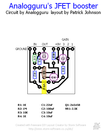
Analogguru - FET-Booster
- analogguru
- Old Solderhand
Information
- soulsonic
- Old Solderhand
Information
Maybe because it's designed to be used as a switch, not an audio amp. I think they sound good in small amounts, but I'm currently breadboarding a thing that has 5 of 'em and their industrial nature is certainly beginning to show  . But personally, I've had better luck getting them to bias up nice than I have had with JFETs - but maybe I'm just an idiot. The only thing I've been able to get to work good with JFETs are mu-amps. But I'll give AG's JFET booster a try and see if it behaves better for me than my previous attempts.
- markm
- Diode Debunker
Wasn't the MPF102's purpose the same.....a switch?soulsonic wrote:Maybe because it's designed to be used as a switch, not an audio amp.
Those are used quite a bit for amplification as well.
- bajaman
- Old Solderhand
Information
- Posts: 4549
- Joined: 26 Jun 2007, 21:18
- Location: New Brighton, Christchurch, NZ
- Has thanked: 596 times
- Been thanked: 2061 times
I think AG is refering to the way it is biased - but I may be wrong - he is the mosfet expert 
- modman
- a d m i n
Information
- Posts: 4897
- Joined: 19 Jun 2007, 16:57
- Has thanked: 4410 times
- Been thanked: 2139 times
Did anybody breadboard this yet?
I did, using a J201 transistor, and I got a very good clean boost from this circuit. However, although I followed and checked over and over:
- the bias pot functions as a gain control (bias is 5.13V at maximum gain and 8.70V at minimum gain (8.87V battery)
- the gain pot doesn't influence the sound or level in any audible way.
- the gain pot crackles!
- BF2415C (didn't have BF245A as suggested) didn't work (GSD pinout I know)
- Jfet that work are 2N5457 (less gain) and then I suppose MPF102, but didn't try that. K170, J112, J111, 2N3819 weren't useable either.
Note that gain and bias pot are parallel pots. 5KB for bias pot (functioning as gain control) work better than lower values, but about to just drop the original 'gain control'
Can anybody see what's going on here. I might have been stupid but it's boosting perfectly with a pot, cap and resistor less.
Maybe I should create my own project "Crackling JFETSHO"? I just hope AG doesn't find out or he'll sue me. You know how he is... You know you only need one building block to get started...
I did, using a J201 transistor, and I got a very good clean boost from this circuit. However, although I followed and checked over and over:
- the bias pot functions as a gain control (bias is 5.13V at maximum gain and 8.70V at minimum gain (8.87V battery)
- the gain pot doesn't influence the sound or level in any audible way.
- the gain pot crackles!
- BF2415C (didn't have BF245A as suggested) didn't work (GSD pinout I know)
- Jfet that work are 2N5457 (less gain) and then I suppose MPF102, but didn't try that. K170, J112, J111, 2N3819 weren't useable either.
Note that gain and bias pot are parallel pots. 5KB for bias pot (functioning as gain control) work better than lower values, but about to just drop the original 'gain control'
Can anybody see what's going on here. I might have been stupid but it's boosting perfectly with a pot, cap and resistor less.
Maybe I should create my own project "Crackling JFETSHO"? I just hope AG doesn't find out or he'll sue me. You know how he is...
Please, support freestompboxes.org on Patreon for just 1 pcb per year! Or donate directly through PayPal
The circuit is very simple. TP1 sets a fixed bias voltage on the collector and a fixed voltage on the base. Gain is then adjusted by the gain-pot. If gain is increased it doesn't alter the bias setting.
The SHO circuit is quite different and has a floating bias voltage on the collector and a floating base voltage, depending on the gain setting.
If you increase the gain the bias and base voltage is altered too
JHS
The SHO circuit is quite different and has a floating bias voltage on the collector and a floating base voltage, depending on the gain setting.
If you increase the gain the bias and base voltage is altered too
JHS
- polarbearfx
- Resistor Ronker
anyone have a layout of this boost?
- modman
- a d m i n
Information
- Posts: 4897
- Joined: 19 Jun 2007, 16:57
- Has thanked: 4410 times
- Been thanked: 2139 times
That's what you would think looking at the schematic, or rather infer from the controls. I'm saying I breadboarded the circuit and it works with bias pot (in shcematic) functioning as gain pot by changing the bias on the drain.JHS wrote:The circuit is very simple. TP1 sets a fixed bias voltage on the collector and a fixed voltage on the base. Gain is then adjusted by the gain-pot. If gain is increased it doesn't alter the bias setting.
Breadboard it and see what you get!JHS wrote:a floating bias voltage on the collector and a floating base voltage, depending on the gain setting.
If you increase the gain the bias and base voltage is altered too
Please, support freestompboxes.org on Patreon for just 1 pcb per year! Or donate directly through PayPal
- Meanderthal
- Breadboard Brother
Information
- Posts: 77
- Joined: 03 Sep 2007, 22:24
Aw, c'mon, that's what 2N404a were designed(and used) for, and they're a sweet sounding tranny... far superior to any of the AC128 I've tried.Maybe because it's designed to be used as a switch, not an audio amp.
Heh- Mark beat me to it with a more appropriate example. Also... what about all those CMOS based circuits?Wasn't the MPF102's purpose the same.....a switch?
Nice little circuit analogguru. And, no crackle!
- analogguru
- Old Solderhand
Information
At the end of the week I will be at home - so in short for now:
The bias poti will have an influence on the gain - the gain poti shouldn´t have an influence on the bias.
By choosing the FET have a look at the Vgs to make it run.
A 2SK 30A should also work in this circuit.
analogguru
The bias poti will have an influence on the gain - the gain poti shouldn´t have an influence on the bias.
By choosing the FET have a look at the Vgs to make it run.
A 2SK 30A should also work in this circuit.
analogguru
There´s a sucker born every minute - and too many of them end up in the bootweak pedal biz.
- modman
- a d m i n
Information
- Posts: 4897
- Joined: 19 Jun 2007, 16:57
- Has thanked: 4410 times
- Been thanked: 2139 times

where are my breadboard brothers?
Please, support freestompboxes.org on Patreon for just 1 pcb per year! Or donate directly through PayPal
- polarbearfx
- Resistor Ronker
AG now how about a killer NPN based boost. single knob.
- analogguru
- Old Solderhand
Information
I don´t know what it should do....and I also don´t know what should be "killer" ... with a single trqansistor NPN boost.AG now how about a killer NPN based boost. single knob.
You can make a treble boost (Rangemaster, Brian May), a bass boost (Vox, EH), a full-range-boost (LPB-1, Big Muff output stage)....
It can distort like one big-muff stage....
You can easily convert every transistor-stage to noise-free (with a gain of 0)..... that could be "killer"...
analogguru
There´s a sucker born every minute - and too many of them end up in the bootweak pedal biz.
- polarbearfx
- Resistor Ronker
npn, it would be cool if it was loud and clean and sparkly I like npn's because with the vox and el84's to me they sound better than mosfets. I like rangemasters, but I like fullrange boosts like the "orman" mosfet boost. So if one could create an NPN version like this, that maybe cool. 1 knob for gain. Loud and clean and sparkly(not ice pick). Feeding that into a vox will be sweet. It would be like a modern day brian may.
- polarbearfx
- Resistor Ronker
I guess NPN is just not popular unless its a rangemaster. Fets year after year still raging.
Information
- Posts: 6
- Joined: 04 Nov 2007, 17:43
Try the beginner project over at DIYstompboxes for a simple NPN boost just like you described. I can take a look inside of mine to see what transistor I decided on after trying 4 or 5 but it compliments my AC15type amp beautifully and sounds great. I figured for a long time that since it was a "beginner" project it wasn't worth my time, but that little boost is actually one hell of a pedal.
- analogguru
- Old Solderhand
Information
Sorry, but the circuit has NOT been designed by Analogman....Barcode wrote:here is an unverified layout i just slapped together, feel free to use it, but please let me know if you build it and it works
analogguru
There´s a sucker born every minute - and too many of them end up in the bootweak pedal biz.


