I was wondering, does anyone have a schematic for the basic circuit EMG uses in their active pickups? It looks like it would be a hard trace since it's totally encapsulated in epoxy, but maybe someone has a factory scheme?
I've been looking at their website, and it seems like they give enough basic info to be able to reverse engineer a workalike. I'm gonna start messing with it this weekend. I have this idea for a project I want to do about DIY "EMG-ing" a passive pickup to work like an EMG. I understand the EMG coils are of a different character to suit the active circuit, but I think it would be a fun retrofit/rework/rewire DIY thing to try.
Any info or suggestions?
EMG Active Pickup Circuit?
I found it somewhere (probably at diystompboxes.com):
"Just a little FYI for everyone: the EMG SPC booster (Strat Presence Control) is virtually identical to the EC Strat midboost. Which came first, I don't know, but they're the same. Which is not that surprising really, since it's a dead simple cookbook type circuit!
In terms of differences/changes, I didn't completely reverse engineer the EMG SPC since it's all SMD and SMD makes my eyes cross Smiley Anyway the circuit values should be chosen to get the boost in a frequency range you like - just play with the RC combinations at the output (the low pass filter) and the - input on the opamp (high pass filter). Some highlights:
- the EMG SPC uses a TL061 opamp, while the EC midboost uses three transistors configured as an opamp. Given that EMG pickups are low noise to begin with (-90dbV) going for low power in a booster (rather than low noise with a TL071) is acceptable.
- 25k mix pot and low resistor values everywhere (lower noise)
- no pre-volume control transistor buffer (pickups are connected directly to the volume control). Normal since the EMG pickups have preamps built directly into them, while the Lace sensors on the EC Strat do not."
And two more pics (SPC and EXG):
https://img263.imageshack.us/img263/8647/093te4.jpg
https://img81.imageshack.us/img81/7948/7d3gz2.jpg
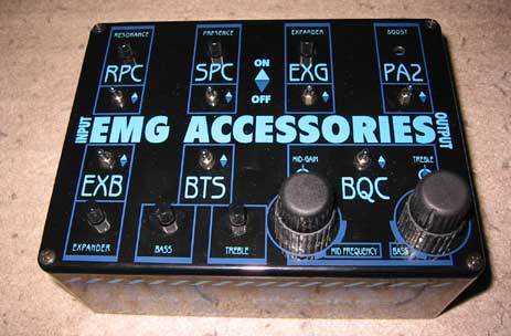
Update: I've just found that those EMG circuits were release as as stand alone pedal. More info here:
http://www.overlend.com/emg-accessories.htm
http://www.overlend.com/images/TheBox1.jpg
"Just a little FYI for everyone: the EMG SPC booster (Strat Presence Control) is virtually identical to the EC Strat midboost. Which came first, I don't know, but they're the same. Which is not that surprising really, since it's a dead simple cookbook type circuit!
In terms of differences/changes, I didn't completely reverse engineer the EMG SPC since it's all SMD and SMD makes my eyes cross Smiley Anyway the circuit values should be chosen to get the boost in a frequency range you like - just play with the RC combinations at the output (the low pass filter) and the - input on the opamp (high pass filter). Some highlights:
- the EMG SPC uses a TL061 opamp, while the EC midboost uses three transistors configured as an opamp. Given that EMG pickups are low noise to begin with (-90dbV) going for low power in a booster (rather than low noise with a TL071) is acceptable.
- 25k mix pot and low resistor values everywhere (lower noise)
- no pre-volume control transistor buffer (pickups are connected directly to the volume control). Normal since the EMG pickups have preamps built directly into them, while the Lace sensors on the EC Strat do not."
And two more pics (SPC and EXG):
https://img263.imageshack.us/img263/8647/093te4.jpg
https://img81.imageshack.us/img81/7948/7d3gz2.jpg
Update: I've just found that those EMG circuits were release as as stand alone pedal. More info here:
http://www.overlend.com/emg-accessories.htm
http://www.overlend.com/images/TheBox1.jpg
-
soulsonic

- Old Solderhand
Information
The main thing I'm interesting in learning about is the actual circuit inside the pickup case.
-
Nikifena

- Solder Soldier
http://www.picvalley.net/u/464/115788_577.JPG
I found in some russian forum over the net.
PS:
Also I make a pictures of EMG booster from a Kerry King from slayer set: KFKSET

http://www.picvalley.net/u/500/124989_947.JPG
Pdf with info - here
http://www.emginc.com/downloads/wiringd ... KFKset.pdf
I found in some russian forum over the net.
PS:
Also I make a pictures of EMG booster from a Kerry King from slayer set: KFKSET
http://www.picvalley.net/u/500/124989_947.JPG
Pdf with info - here
http://www.emginc.com/downloads/wiringd ... KFKset.pdf
Information
you ever get anywhere with this project, it sounds interesting !
Signature:
Built = SHO , DOD 250, Atari punk console,Fuzz Factory,Easy Vibe,Burning Crunch,Vm fuzz (2n5088+bmp tonestack),
Wah Probe,Dr.boogie,wolly mammoth
Up Next =
Eventually = Firefly, rackmount L5 preamp
http://dellamorte.gofreeserve.com
Built = SHO , DOD 250, Atari punk console,Fuzz Factory,Easy Vibe,Burning Crunch,Vm fuzz (2n5088+bmp tonestack),
Wah Probe,Dr.boogie,wolly mammoth
Up Next =
Eventually = Firefly, rackmount L5 preamp
http://dellamorte.gofreeserve.com
-
soulsonic
- Old Solderhand
Information
Okay, I hadn't checked this in awhile. Niki's link to the EMG81 circuit has revitalized my interest in this. Thanks Niki! When I get a chance, I will play around with some circuit ideas.
"Analog electronics in music is dead. Analog effects pedal design is a dead art." - Fran
Information
- Posts: 27
- Joined: 10 Mar 2009, 02:34
Hi there, this is an interesting topic since I have a guitar that I recently finiched to mod (floyd to hard-tail and custom graphics) so it would be cool to mess with the electronics now 
Could some one explain to me that 81 schematic? Like, if i have a passive HB how would I use that? I'me kind of a newbe in this matters.
Could some one explain to me that 81 schematic? Like, if i have a passive HB how would I use that? I'me kind of a newbe in this matters.
This doesn't pertain to the preamp within the pickup, but there's a video on youtube called 'Tour of the EMG factory pt.2' or something along those lines.
If you stop it at the right time, it gives you all the information about the EMG 81 coils.
EMOedit:
Kurotenshi, you want to explain what you're asking? I might be able to give you a hand.
If you stop it at the right time, it gives you all the information about the EMG 81 coils.
EMOedit:
Kurotenshi, you want to explain what you're asking? I might be able to give you a hand.
Information
- Posts: 27
- Joined: 10 Mar 2009, 02:34
Basicly what i'm asking is: Can I get my passive HB's and turn them active using that schematic of the EMG 81? and if so, how.
-
puppiesonacid
- Cap Cooler
kurotenshi wrote:Basicly what i'm asking is: Can I get my passive HB's and turn them active using that schematic of the EMG 81? and if so, how.
not really.
-
SPeter
- Cap Cooler
Hi all,
While looking for something different found this:
http://music-electronics-forum.com/t9095/
Note!:You need to register in order to see the pictures!
Enjoy!

While looking for something different found this:
http://music-electronics-forum.com/t9095/
Note!:You need to register in order to see the pictures!
Enjoy!
-
bumblebee

- Diode Debunker
nevermind.
I so dislike the modern digital world that I need to use semi-digital effects to emulate the analog world of cassette, VHS, and vinyl.
-
bajaman

- Old Solderhand
Information
- Posts: 4549
- Joined: 26 Jun 2007, 21:18
- Location: New Brighton, Christchurch, NZ
- Has thanked: 596 times
- Been thanked: 2061 times
I have been playing round with the SPC and RPC controls (simulations only).
Does anyone have any more info including higher res pictures of the components etc.
By the way - the SPC uses an LF441 low current draw op amp not the TL061 (at least not in the pictures I have seen on the net and EMG's site.
Any info would be appreciated.
 Cheers
bajaman
Does anyone have any more info including higher res pictures of the components etc.
By the way - the SPC uses an LF441 low current draw op amp not the TL061 (at least not in the pictures I have seen on the net and EMG's site.
Any info would be appreciated.
bajaman
be kind to all animals - especially human beings
-
bajaman
- Old Solderhand
Information
- Posts: 4549
- Joined: 26 Jun 2007, 21:18
- Location: New Brighton, Christchurch, NZ
- Has thanked: 596 times
- Been thanked: 2061 times
Okay - no panic - a friend lent me his guitar loaded with the EMG RPC and SPC controls and of course I traced and measured them - i have pictures and I have layouts etc - up in a few days - I built an RPC control and installed it in one of my strats (the one with two EMG81 pickups etc.) and I have to say it works very well in sharpening the top end response to mimic a more Telecaster type of tone.
Before i go any further i would like to comment on the EMG81 pickups.
Earlier in this thread is a schematic for the preamp encapsulated in the baseplate of the EMG81.
Referring to this scheme it is easy to see that it is a classic differential amplifier circuit stage - any noise or hum appearing on both coils gets attenuated in the same ratio as the overall gain. In simple terms we end up with a very quiet and super humbucking pickup, BUT in the EMG81's case there exists a slight imbalance in the differential arms. Although both coils feed via 22n dc isolating coupling capacitors, the coil connected to the non inverting input is missing it's source resistor - in the schematic's case 30k. In practice this will not make much difference if any to the noise cancelling efficiency but it will create some imbalance of signal gain in the higher frequency region where the rising coil inductances come into play.
Okay so how does the pickup sound - it is one of the favoured metal player's pickups.
i was quite surprised to hear that it sounds very much like a single coil pickup - with very high voltage output and extremely quiet especially with the proceeding 25k log volume control turned down some.
There is absolutely none of that PAF humbucker squark you get on the first few frets of the bottom E string on your guitar.
Could this be the infamous EMG "tone modeling" at work. The EMG website claims that only a small amount of tone modelling is applied with the 81 pickup - is this the missing 30k effect????
We will probably never know because you cannot disassemble an EMG81 without breaking the coil wires, so don't try it!!!
Anyway, I found some more pictures of an opened EMG81 on another forum and it is clear to see that the place for the missing 30k resistor is there on the board but is loaded with a 0 ohm link smd resistor.
My theory is that EMG use this same schematic in all their guitar pickups but some models may have different resistor values - perhaps 2 x 30k resistors.
Other models may also have differing coupling capacitors to alter low end reponse etc.- who knows?? worth experimenting with.
Anyway - I built an active preamp based on the pictures and the schematic and I have attached it to the underside of a cheap Chinese Ceramic Humbucking pickup - I wanted to retain the humbucker's squark so i used a balanced differential amplifier using 39k input resistors and 2 x 330k bias resistors for the non inverting input. For the feedback resistor in the inverting mode I used a 150k and 15k series resistor combination.
unfortunately i do not have a guitar i can put it on at the present time but when I connected a 25k volume pot and a flying lead to my amplifier i was pleasantly surprised at the low noise and clarity of the pickup.
more later when i have it installed in a guitar.
i will post the board layout etc. very soon for anyone else who wishes to make their own active humbucking pickups.
cheers
bajaman
be kind to all animals - especially human beings
>>>>> the coil connected to the non inverting input is missing it's source resistor
this will inevitably "bypass" the non-existing resistors' thermal noise contribution - and resistor noise wouldn't cancel as effectivelly in a diff. amp //naivelly speaking
this will inevitably "bypass" the non-existing resistors' thermal noise contribution - and resistor noise wouldn't cancel as effectivelly in a diff. amp //naivelly speaking
-
bajaman
- Old Solderhand
Information
- Posts: 4549
- Joined: 26 Jun 2007, 21:18
- Location: New Brighton, Christchurch, NZ
- Has thanked: 596 times
- Been thanked: 2061 times
members/bajaman/Baja/Active%20preamp%20info/
The first five images show my Chinese active humbucker premp built on veroboard (on the copper side).
When I had assembled all the components I filed the other side of the veroboard flat, then attached the preamp with glue to the back plate of the pickup - I used a strip of mylar overhead transparency film as an insulator.
I broke the series wire connection between the two coils and reattached each red wire through the baselate hole and connected to the two 22n coupling capacitors - both the other coil wires (white) were soldered directly to the baseplate.
The veroboard was connected at each end of the ground trace to the baseplate also! Note the series composite resistor combination (150k + 15k) in the first and fifth pictures.
The other files are DIY layout creator layouts and some photos of the EMG SPC and RPC boards fitted in my friend's strat.
more on these later
cheers
bajaman
be kind to all animals - especially human beings