Honey - Special Fuzz  [schematic]

Discussion regarding early stompbox technology: 1960-1975 Please keep discussion focused and contribute what info you have...
User avatar
digi2t
Degoop Doctor
Information
Posts: 284
Joined: 09 Feb 2011, 15:10
Has thanked: 54 times
Been thanked: 385 times

Post by digi2t »

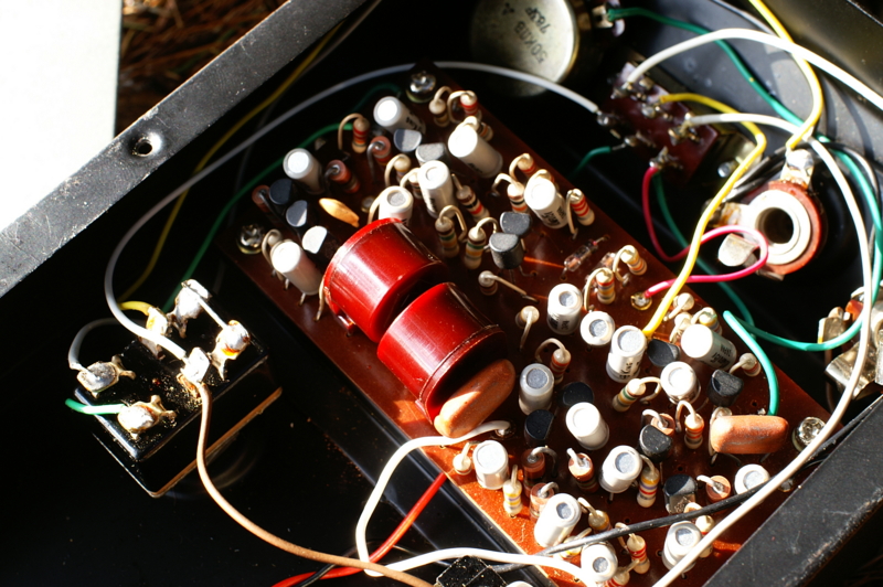
I came across this fuzz box recently, the Honey Special Fuzz;

Image

Image

Image

It's got me MAJORLY intrigued :icon_eek: :icon_eek: :icon_eek:. I did a search, and it has been discussed here before.

I would love to breadboard/clone this sucker, but I need to find someone out there whos got one.

Anybody out there got one?

Thanks,
Dino
No matter how many times I cut it, it`s STILL too short!

https://www.deadendfx.com/

User avatar
azrael
Cap Cooler
Information
Posts: 564
Joined: 02 Jun 2009, 14:07
Has thanked: 35 times
Been thanked: 88 times

Post by azrael »

WOW, so many transistors. And what are the inductors for?

I am hoping to see more light shone on this one.

User avatar
briggs
Tube Twister
Information
Posts: 1971
Joined: 12 Jul 2007, 10:02
my favorite amplifier: Briggs Custom Suprono
Completed builds: Too many to still class myself as sane....
Location: Breaking into Heaven.
Has thanked: 27 times
Been thanked: 128 times
Contact:

Post by briggs »

Image

I am Klon.

User avatar
digi2t
Degoop Doctor
Information
Posts: 284
Joined: 09 Feb 2011, 15:10
Has thanked: 54 times
Been thanked: 385 times

Post by digi2t »

Hi guys.

Just in case someone doesn't follow what's going on over at the "other forum", here's an update. The pedal in action;


The component side;

Image

The trace side with components labeled;

Image

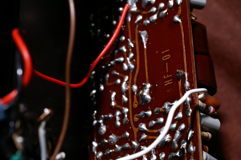
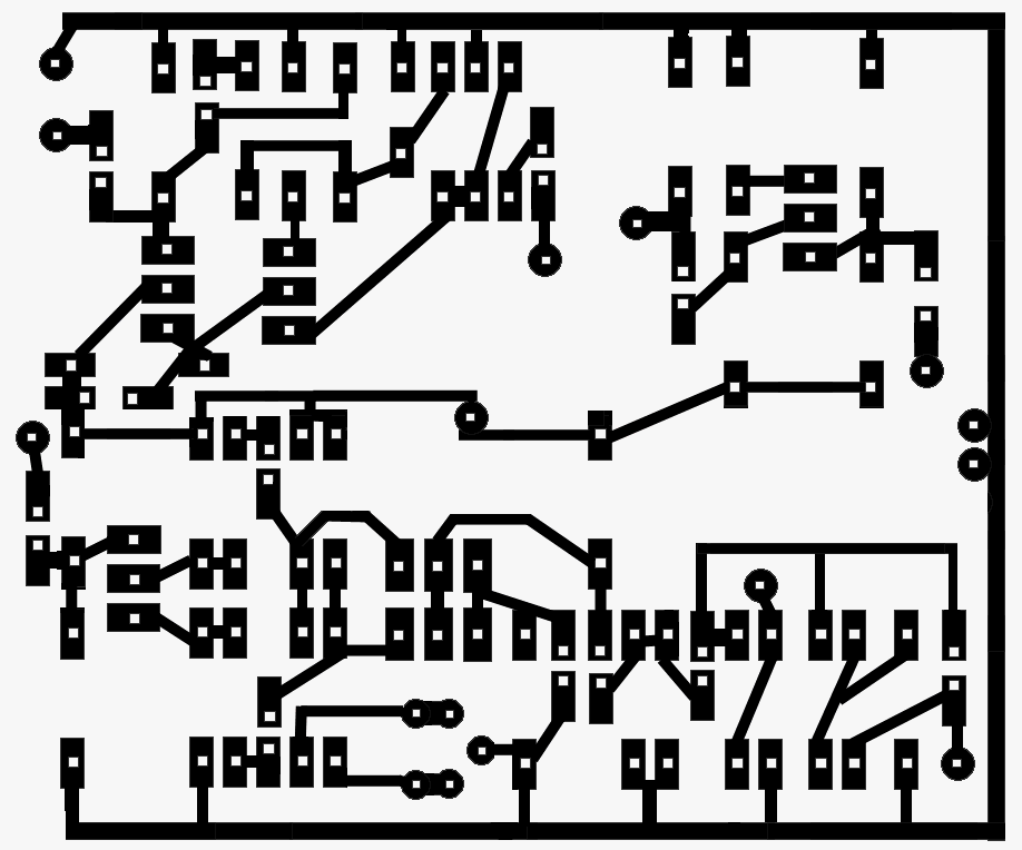
And two trace side shots, for you PCB etchers;

Image

Image

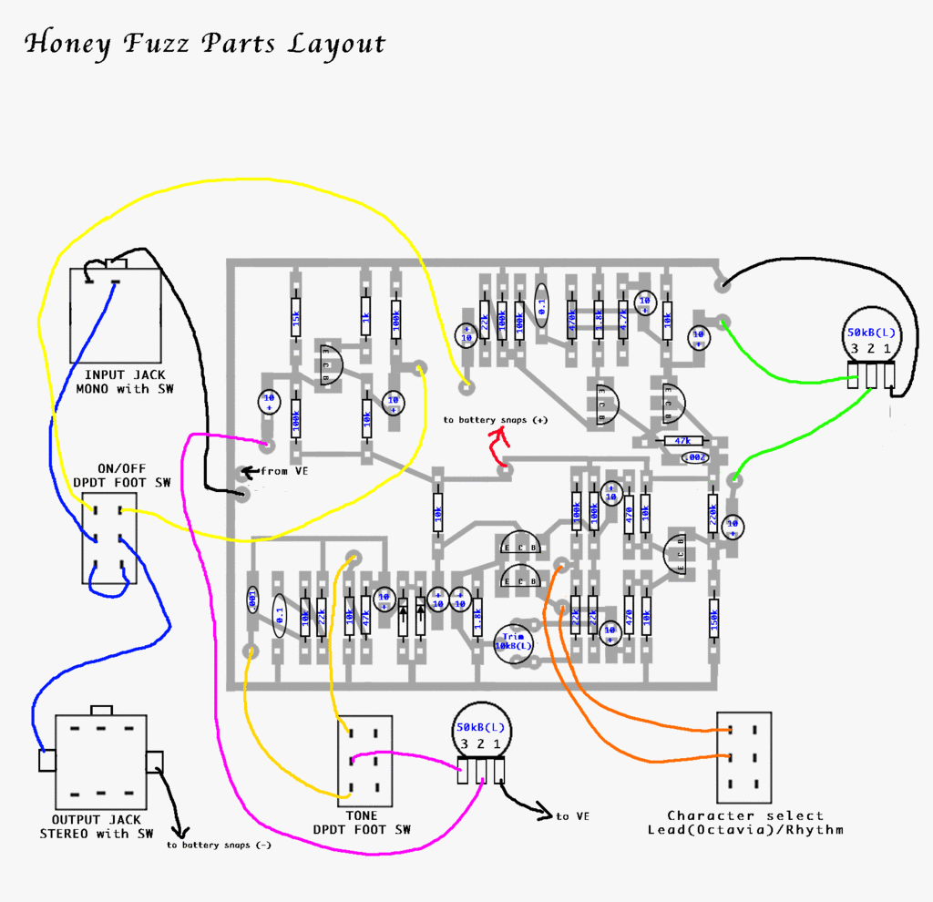
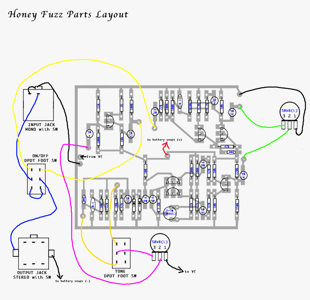
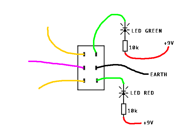
I'll get the wiring diagram up soon.

Cheers,
Dino
No matter how many times I cut it, it`s STILL too short!

https://www.deadendfx.com/

User avatar
digi2t
Degoop Doctor
Information
Posts: 284
Joined: 09 Feb 2011, 15:10
Has thanked: 54 times
Been thanked: 385 times

Post by digi2t »

Just noticed that there is a resistor missing on the trace side picture.... DOAH!!!

Split the picture in quarters, in the upper left quadrant, smack dab in the middle. There are two bare pads, surrounded by 2 trannies, two 10uF caps, a 1M and 4.7K resistors. There is a 1M resistor missing between the pads here.

I'll update the image asap, I'm working night shifts right now.

Sorry folks :oops:
No matter how many times I cut it, it`s STILL too short!

https://www.deadendfx.com/

User avatar
Dirk_Hendrik
Old Solderhand
Information
Posts: 4193
Joined: 03 Jul 2007, 08:44
Location: Old Amsterdam
Has thanked: 232 times
Been thanked: 888 times
Contact:

Post by Dirk_Hendrik »

digi2t wrote:I'll get the wiring diagram up soon.
Thanks for the heads up!
Please do. There's some stuff that makes hard earscratching. Knowing the switches connections might help. As well as better demos that clearly show the sonic differences between settings (and less blablabla). While reading the diystomps thread I was rather amazed nobodu even attempted to draw a schem.

If you follow the white wire it goes to a 1uF and a 47k. It does not go to anything else like in the "transparent" picture :blackeye. And there's 2 resistors which one would expect to be the same.
Tracesidecomponents.jpg
Sorry. Plain out of planes.

http://www.dirk-hendrik.com

User avatar
digi2t
Degoop Doctor
Information
Posts: 284
Joined: 09 Feb 2011, 15:10
Has thanked: 54 times
Been thanked: 385 times

Post by digi2t »

Thanks for your astute observation on the cut in the trace Dirk, you're absolutely correct. My bad, I took the picture, and then ran with it. Looking back at the board, there is a cut there. As for the resistors, I checked them again, and they are as in the picture (should change shortly, Photobucket is slow).

I've updated the picture, and here is the wiring;

Image
No matter how many times I cut it, it`s STILL too short!

https://www.deadendfx.com/

User avatar
Dirk_Hendrik
Old Solderhand
Information
Posts: 4193
Joined: 03 Jul 2007, 08:44
Location: Old Amsterdam
Has thanked: 232 times
Been thanked: 888 times
Contact:

Post by Dirk_Hendrik »

OK... here's my shot. Screams for some simulations.

Honey Special Fuzz Schematic

The input stage before the filter has a very strong resemblance to the input stage of the Shin-Ei Resleytone (Univibe for most). That, plus the really odd circuit that does the filtering, suggests Fumio Mieda may have had a hand in this one.
Sorry. Plain out of planes.

http://www.dirk-hendrik.com

User avatar
analogguru
Old Solderhand
Information
Posts: 3238
Joined: 26 Jun 2007, 13:58
Been thanked: 124 times
Contact:

Post by analogguru »

only for the record before simulation efforts will begin: R5 = 2k2, R25 = 4k7

analogguru
There´s a sucker born every minute - and too many of them end up in the bootweak pedal biz.

User avatar
digi2t
Degoop Doctor
Information
Posts: 284
Joined: 09 Feb 2011, 15:10
Has thanked: 54 times
Been thanked: 385 times

Post by digi2t »

analogguru wrote:only for the record before simulation efforts will begin: R5 = 2k2, R25 = 4k7

analogguru
Also C1 = 10uF.

Thanks analogguru.
No matter how many times I cut it, it`s STILL too short!

https://www.deadendfx.com/

User avatar
Dirk_Hendrik
Old Solderhand
Information
Posts: 4193
Joined: 03 Jul 2007, 08:44
Location: Old Amsterdam
Has thanked: 232 times
Been thanked: 888 times
Contact:

Post by Dirk_Hendrik »

Updated. Thanks gents!
Sorry. Plain out of planes.

http://www.dirk-hendrik.com

User avatar
digi2t
Degoop Doctor
Information
Posts: 284
Joined: 09 Feb 2011, 15:10
Has thanked: 54 times
Been thanked: 385 times

Post by digi2t »

OK, I'm half way to doing a vero of the Ludwig :shock: .

This must be the most complex vero I've ever done, at 13 trannies (not to mention the two 42TL019 audio transformers!). For some bizarre reason, it was almost one of my fastest. I dunno, so don't ask. Here it is;

Image

It's using the same component numbers as Dirk's schematic, and the wire connection numbers as my wiring drawing.
No matter how many times I cut it, it`s STILL too short!

https://www.deadendfx.com/

User avatar
nightraven
Breadboard Brother
Information
Posts: 149
Joined: 21 Jul 2009, 18:38
Location: UK
Has thanked: 17 times
Been thanked: 97 times

Post by nightraven »

Dirk_Hendrik wrote:OK... here's my shot. Screams for some simulations.

Honey Special Fuzz Schematic

The input stage before the filter has a very strong resemblance to the input stage of the Shin-Ei Resleytone (Univibe for most). That, plus the really odd circuit that does the filtering, suggests Fumio Mieda may have had a hand in this one.
That would make sense because the Resleytone/Univibe etc was originally a Honey design :thumbsup
https://fuzzboxes.org | authoritative and clickbait-free resource for 1960s fuzz pedals

User avatar
sinner
Old Solderhand
Information
Posts: 4709
Joined: 06 Nov 2008, 17:16
Location: ...no more
Has thanked: 1031 times
Been thanked: 909 times

Post by sinner »

digi2t wrote:OK, I'm half way to doing a vero of the Ludwig :shock: .

This must be the most complex vero I've ever done, at 13 trannies (not to mention the two 42TL019 audio transformers!). For some bizarre reason, it was almost one of my fastest. I dunno, so don't ask. Here it is;

Image

It's using the same component numbers as Dirk's schematic, and the wire connection numbers as my wiring drawing.
Sweet Cizus Mother Love Bone :!:

:thumbsup

User avatar
digi2t
Degoop Doctor
Information
Posts: 284
Joined: 09 Feb 2011, 15:10
Has thanked: 54 times
Been thanked: 385 times

Post by digi2t »

Sweet Cizus Mother Love Bone
LOL... kinda sorta what crossed my mind when I was done. :lol:

Info - I recieved my capacitance/inductance meter today, and I tried out the primary side of a few 42TL019 transformers today. They all came in between 4.3 and 4.9 Henry. They should be suitable stand-in`s as inductors, in place of the TDK`s which I have had no success in finding.

The only thing I`m wondering now is if I should make room for a balancing trimmer between the two trannies in the octave section, a la Super Fuzz. That, and maybe jazzing things up with a fuzz intensity pot.

Still working on the phase rate side of things.
No matter how many times I cut it, it`s STILL too short!

https://www.deadendfx.com/

User avatar
John Lyons
Solder Soldier
Information
Posts: 191
Joined: 18 Aug 2007, 03:09
Location: West Virginia
Has thanked: 5 times
Been thanked: 30 times

Post by John Lyons »

The octave/balance is fine when you match the transistors Hfe and use tight tolerance resistors to ground
(22Ks). Some folks like to imbalance that section to get a little less octave so I guess it's up to you whether you
want control over the octave or want it set strong. I don't think it warrants a panel pot but...

User avatar
digi2t
Degoop Doctor
Information
Posts: 284
Joined: 09 Feb 2011, 15:10
Has thanked: 54 times
Been thanked: 385 times

Post by digi2t »

I don't think it warrants a panel pot but...
No, not a panel pot. It's not worth it, but a trimmer might be "a good thing" if someone is building it with looser tolerances. I would have to rework the layout though, but there is some room for a trimmer beside L1.

Speaking of which, I spotted a couple of errors, which I corrected on the first layout. I had a couple of resistors going the wrong way. Also, I've managed to reduce the size of the board slightly. Here is the layout with the BOM;

Image

Again, still unverified until someone reports a build.
No matter how many times I cut it, it`s STILL too short!

https://www.deadendfx.com/

User avatar
digi2t
Degoop Doctor
Information
Posts: 284
Joined: 09 Feb 2011, 15:10
Has thanked: 54 times
Been thanked: 385 times

Post by digi2t »

OK, I had some time, so I did a triple check, and I did spot some errors. They are now corrected, and I would use this to build with. Here is the updated versions, with and without the BOM.

Image

Image

The smallest enclosures I use are the 1590BB style, so this vero is sized to fit widthwise. I figured that way, if another pot, or switch, enters the fray, they'll still be room.
No matter how many times I cut it, it`s STILL too short!

https://www.deadendfx.com/

User avatar
pinkjimiphoton
Transistor Tuner
Information
Posts: 1242
Joined: 12 Sep 2010, 19:03
my favorite amplifier: my own, a redesigned princeton
Completed builds: so fucking many goddamn pedals it would make your ass hurt just looking at 'em all!!!!!
there's videos that totally suck of about 90 of 'em here:
http://youtube.com/666pinkster
gimme a like: http://facebook.com/pinkjimiphotonrocks
Location: new world order land (formerly la-la land)
Has thanked: 358 times
Been thanked: 480 times
Contact:

Post by pinkjimiphoton »

amazing what ya find surfing the flotsam and jetsam of the internet archive...


http://web.archive.org/web/200204072027 ... slist.html

Image

Image

Image

Image

Image

these two aren't of the honey special fuzz, but hey, in for a dollar....

Image

Image
"When the power of love overcomes the love of power the world will know peace."
Slava Ukraini!

User avatar
agoldoor
Breadboard Brother
Information
Posts: 112
Joined: 26 May 2011, 04:37
Has thanked: 39 times
Been thanked: 21 times

Post by agoldoor »

I wasn't sure if you guys had this one completely traced or not, but there's one on Ebay at the moment:
https://www.ebay.com/itm/RARE-Vintage-1 ... 2c69b9ad43

Just in case you have any additional questions... this guy says he has TWO of these!

Post Reply