EH - Big Muff Pi ( Ram Head, Early Version )

All about modern commercial stompbox circuits from Electro Harmonix over MXR, Boss and Ibanez into the nineties.
User avatar
Fred_Garvin
Information
Posts: 20
Joined: 05 Mar 2011, 20:56
my favorite amplifier: The Giggleplex 9000
Location: In a house...somewhere.
Has thanked: 7 times
Been thanked: 4 times

Post by Fred_Garvin »

I know this thread is dead, but, I'm reviving it because of my build.

I bought a reissue muff a while back and never liked the sound much. So, as I was surfing ebay, my eye caught these V2 muff pcb's made by PigeonFX. I thought, gee, wouldn't it be cool to gut this reissue and make it into something better. So, I checked out Kitrae's site and noticed that he had a picture of a V2 muff with the values labelled. To cut to the chase, I bought the PCB from ebay along with a bunch of parts I won in a previous auction and hunkered down to make a magical muff. I found almost every available part I had lying around except a few, the .15uf capacitor so I opted for a .18uf I had kicking around, and the .004uf which I used a .0047uf. I used BC547C for the trannies at 600-799 hfe. The results are truly night and day, this thing sounds amazing, it even beats out my muff with tone wicker, I like it that much. The tone knob sweep is backwards just like a Ram's head. Here are some pics.

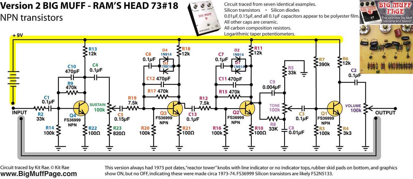
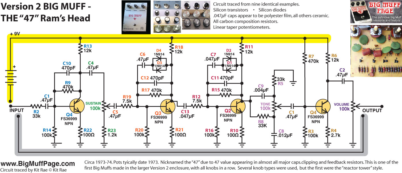
This is the picture I used for reference from Kitrae's site. (Thank you, Kit!)
Image

Pictures of the final project.
Image
Image
Image
Image
Image
Image
Fred Garvin, Male Prostitute.

User avatar
Kitrae
Breadboard Brother
Information
Posts: 102
Joined: 15 Apr 2010, 22:57
Has thanked: 4 times
Been thanked: 29 times

Post by Kitrae »

Your are welcome. Nice build. That RH Muff is one of my favorites. Found the original in a pawn shop in the midwest for a few hundred bucks. The thing is noisy, but it sings.
Kitrae - Muff junkie
Big Muff Page
http://bigmuffpage.com/
Tonbender Timeline
http://www.bigmuffpage.com/The_Tonebender_Timeline.html

User avatar
Fred_Garvin
Information
Posts: 20
Joined: 05 Mar 2011, 20:56
my favorite amplifier: The Giggleplex 9000
Location: In a house...somewhere.
Has thanked: 7 times
Been thanked: 4 times

Post by Fred_Garvin »

Thanks Kit, love your site! If it wasn't for your site I wouldn't have gone forward with the project. As you can see the differences in these things as seen at the beginning of the article, this build has no electrolytic capacitors. Yet, the images I've seen they seem to be all over the map as to regards of parts selection. It's no wonder that they all sound different, there was no consistency, even when it came to keeping to the values in the schematic. I find it very interesting.

You'll notice that one capacitor (big green one) is soldered to the bottom of the pcb because it was to large to fit properly, this being the .18uf (180nf) cap.
Fred Garvin, Male Prostitute.

User avatar
Kitrae
Breadboard Brother
Information
Posts: 102
Joined: 15 Apr 2010, 22:57
Has thanked: 4 times
Been thanked: 29 times

Post by Kitrae »

Fred_Garvin wrote:Thanks Kit, love your site! If it wasn't for your site I wouldn't have gone forward with the project. As you can see the differences in these things as seen at the beginning of the article, this build has no electrolytic capacitors. Yet, the images I've seen they seem to be all over the map as to regards of parts selection. It's no wonder that they all sound different, there was no consistency, even when it came to keeping to the values in the schematic. I find it very interesting.
There was a schematic? :lol:

There does seem to have been some intentional logic to it at times, and other times not. I have traced and dated enough of them now to find that they did make long runs of particular versions that were consistent for a period of time. Whether those periods of time were weeks, months, or up to a year is hard to say. I am guessing several times a year they changed to an alternate set of values. If you just look a V2 (Ram Head) BMP's, there are numerous examples that follow the exact same set of values, and often same component types, all with matching graphics changes/color, knobs, and pot dates for this not to be the case. I think I am up to 4 on the triangle and 6 on the Ram's Head that were made in very long runs. I can almost build a sequence of changes over several years from this, though I'm not sure anyone would be interested in it.

It all leads me to believe this was intentional. It may be intention caused by supply, but it was not all just completely random as most of us assumed in the early days of digging through Muff guts. I have not gotten any real explanation from Mr. Matthews about why this was done. The same practice was applied to other EHX pedals too, including the russian made Big Muffs, and even continues with the current EHX line up. Not to the degree that it was done in the past, but since 2000 there have been three minor changes to the large box BMP circuit, and 2 in the LBM.
Kitrae - Muff junkie
Big Muff Page
http://bigmuffpage.com/
Tonbender Timeline
http://www.bigmuffpage.com/The_Tonebender_Timeline.html

User avatar
boog
Information
Posts: 9
Joined: 17 Aug 2009, 00:59
Has thanked: 6 times

Post by boog »

hey kit, just wanted to say that i find your site to be freaking awesome. if, for whatever reason, you decide to post the series of changes, this nerd would eagerly read it. while i haven't gotten into the vintage muffs (could never fathom paying that kind of cash to just pull something apart), i find it amazing to plug in 3 black bmp's (one with the sovtek switch, one it a big box with a 3pdt, one in a small box) and hear 3 different sounds. i've picked some differences out (unmarked russian trannies vs bc547, film caps vs those paper looking things), just bizarrely incredible.

User avatar
tschrama
Breadboard Brother
Information
Posts: 118
Joined: 17 Aug 2008, 08:39
my favorite amplifier: SE El84 DIY .. :D
Completed builds: Distortion +
Tripple RAT
about 5 Big Muffs
Tubescreamer
JFET simulator
5 Watt SE El84 versions Marshall 2204
5 Watt SE El84 versions Mesa Recto
100W 4xEl34 Mesa Recto
Has thanked: 24 times
Been thanked: 4 times

Post by tschrama »

[quote="Kitrae"].....I think I am up to 4 on the triangle and 6 on the Ram's Head that were made in very long runs. I can almost build a sequence of changes over several years from this, though I'm not sure anyone would be interested in it.....quote]

:!: Offcourse people would be interested in a chronological sequence of changes :!:

Big thanks for your great website. and as a real fx-thickerer, and for one would be very interested in a reconstruction of the sequence of changes of the Big Muff circuit. It would greatly help to sort out what makes a BMP sound good (to me) and makes it sound less good.

grtzz,
Thijs
Build your own 50W, three channel, amp in just two days at www.sgravenmade.com

Copyright does not protect facts, ideas, systems, or methods of operation, although it may protect the way these things are expressed. US Copyright Office

User avatar
billgraam
Information
Posts: 13
Joined: 24 May 2011, 12:58
Has thanked: 1 time

Post by billgraam »

Hi all!!
Im sorry if I open again this old thread...
I've a problem..
I've built the same ram's head with the same vintage circuit, the same values ​​used by fred_garvin (lot of compliments) indicated by Kitrae .. but with different transistors: 2n5088 and Hfe around 500
My ram's sounds very good, but it sounds like a hi-gain distortion, and not as a muff ..no fuzzing sound...
It could be the HFE too low? Fred has used trannys with hfe around 700...
These are the values ​​measured for the transistors:
q1) C: 4.03V B: 0.63V E: 0.03
q2) C: 4.11V B: 0.60V E: 0.06
q3) C: 4.13V B: 0.62V E: 0.03
q4) C: 4.66V B: 1.66V E: 1.20
I checked the circuit and measured each resistor
I'm going crazy :slap:
anyone can help me?
p.s im sorry for my bad english..

User avatar
billgraam
Information
Posts: 13
Joined: 24 May 2011, 12:58
Has thanked: 1 time

Post by billgraam »

billgraam wrote:Hi all!!
Im sorry if I open again this old thread...
I've a problem..
I've built the same ram's head with the same vintage circuit, the same values ​​used by fred_garvin (lot of compliments) indicated by Kitrae .. but with different transistors: 2n5088 and Hfe around 500
My ram's sounds very good, but it sounds like a hi-gain distortion, and not as a muff ..no fuzzing sound...
It could be the HFE too low? Fred has used trannys with hfe around 700...
These are the values ​​measured for the transistors:
q1) C: 4.03V B: 0.63V E: 0.03
q2) C: 4.11V B: 0.60V E: 0.06
q3) C: 4.13V B: 0.62V E: 0.03
q4) C: 4.66V B: 1.66V E: 1.20
I checked the circuit and measured each resistor
I'm going crazy :slap:
anyone can help me?
p.s im sorry for my bad english..
a little demo :
http://www.mediafire.com/?59t0lh0jg64t4f8

User avatar
billgraam
Information
Posts: 13
Joined: 24 May 2011, 12:58
Has thanked: 1 time

Post by billgraam »

no idea??? :(

User avatar
blackbunny
Resistor Ronker
Information
Posts: 372
Joined: 07 Jan 2011, 07:41
my favorite amplifier: Fender Blackface
Completed builds: Lots of mods to lots of pedals
Location: the garage
Has thanked: 270 times
Been thanked: 108 times

Post by blackbunny »

billgraam wrote:I've built the same ram's head with the same vintage circuit, the same values ​​used by fred_garvin (lot of compliments) indicated by Kitrae .. but with different transistors: 2n5088 and Hfe around 500
My ram's sounds very good, but it sounds like a hi-gain distortion, and not as a muff ..no fuzzing sound...
It could be the HFE too low? Fred has used trannys with hfe around 700...
Could it be that you put the 2N5088's in the wrong way around? 2N5088 has the opposite pinout of BC547...just a thought.

User avatar
Kitrae
Breadboard Brother
Information
Posts: 102
Joined: 15 Apr 2010, 22:57
Has thanked: 4 times
Been thanked: 29 times

Post by Kitrae »

billgraam wrote:Hi all!!
Im sorry if I open again this old thread...
I've a problem..
I've built the same ram's head with the same vintage circuit, the same values ​​used by fred_garvin (lot of compliments) indicated by Kitrae .. but with different transistors: 2n5088 and Hfe around 500
My ram's sounds very good, but it sounds like a hi-gain distortion, and not as a muff ..no fuzzing sound...
It could be the HFE too low? Fred has used trannys with hfe around 700...
This may be a problem of differing definitions of fuzz or distortion, but the Big Muff is a high gain distortion circuit. "Fuzzing sound" could mean many things, but if you were expecting fuzz tones like a Fuzz Face type circuit, that is quite a bit different from a Big Muff sound. I don't know what type of amp or guitar pickups you used for your sound clip, but that sounded like a Big Muff to me.
Kitrae - Muff junkie
Big Muff Page
http://bigmuffpage.com/
Tonbender Timeline
http://www.bigmuffpage.com/The_Tonebender_Timeline.html

User avatar
billgraam
Information
Posts: 13
Joined: 24 May 2011, 12:58
Has thanked: 1 time

Post by billgraam »

Hi all!! tnx for the answers....

@ blackbunny: transistors are connected in the right way, unfortunately :cry:
@ Kit: i love you site...great...
yes, maybe I've used the wrong word, my english is very poor. ... perhaps the proper term is not fuzzin...but saturation...
My muff has great distortion, great sustain and volume...but...
at my ears, lacks of high frequency.....and dont sound like a muff...so im thinking that the problem is the low hfe in my trannys...
I've another big muff and it sounds like a muff must sound..and very different from my ram's...
Tomorrow i'll install new transistors with high hfe... ..and make a litte sample...is easier to understand
My amp is a blues deluxe and my pups are custom shop 69...with this instruments, my other muff sound like a muff...so in think that i've a problem with my ram's... :cry:
Ok..tnx for the answers
I hope to still disturbing with another post..tomorrow...
bye...

User avatar
bato001
Resistor Ronker
Information
Posts: 322
Joined: 19 Feb 2009, 21:31
Location: NJ
Has thanked: 31 times
Been thanked: 38 times

Post by bato001 »

Replace the the cap between Q2 and Q3 with a .1uF electrolytic, positive side towards Q3. This has become my standard setup for Big Muff Pi circuits as it causes a mediocre sounding build to bloom into thick, fuzzy goodness.
"Ever wondered how some of your favourite guitar players got their tone? Me too. Probably a good amp and lots of practice." Little Lord Electronics Homepage

User avatar
bato001
Resistor Ronker
Information
Posts: 322
Joined: 19 Feb 2009, 21:31
Location: NJ
Has thanked: 31 times
Been thanked: 38 times

Post by bato001 »

bato001 wrote:Replace the the cap between Q2 and Q3 with a .1uF electrolytic, positive side towards Q3. This has become my standard setup for Big Muff Pi circuits as it causes a mediocre sounding build to bloom into thick, fuzzy goodness.

Positive towards Q2, sorry!!!!!
"Ever wondered how some of your favourite guitar players got their tone? Me too. Probably a good amp and lots of practice." Little Lord Electronics Homepage

User avatar
billgraam
Information
Posts: 13
Joined: 24 May 2011, 12:58
Has thanked: 1 time

Post by billgraam »

yep Bato :wink: tnx for the answer..i will do tomorrow...
i hope this solves :thumbsup

User avatar
guitarmongot
Breadboard Brother
Information
Posts: 106
Joined: 09 Jun 2009, 21:44
Location: Sweden
Has thanked: 15 times
Been thanked: 10 times

Post by guitarmongot »

Hi Billgraam.
You should also try : Compressor-BigMuff-OD (eg OCD,TS or simular).
I´ve buildt a V2 BigMuff with NOS trannies (300-400 hfe) and if your
going for Smashing Pumpkin tone : you need to push your tube amp with
a lot of volume (LOUD)....
If you devide gain stages into 3 pedals....it´s easier to dial in a smooth fuzzy distortion
with that Big Muff endless sustain...
/cheers M

User avatar
billgraam
Information
Posts: 13
Joined: 24 May 2011, 12:58
Has thanked: 1 time

Post by billgraam »

Hi guitarmongot...i will try...
I'm trying to get a good base with my muff.. after...I will try many configurations with my pedals...thanks for your answer :mrgreen:

User avatar
billgraam
Information
Posts: 13
Joined: 24 May 2011, 12:58
Has thanked: 1 time

Post by billgraam »

bato001 wrote:Replace the the cap between Q2 and Q3 with a .1uF electrolytic, positive side towards Q3. This has become my standard setup for Big Muff Pi circuits as it causes a mediocre sounding build to bloom into thick, fuzzy goodness.
hem Bato...you means C13 in Kit's schematics..right??
tnx :wink:
http://www.kitrae.net/music/Images_Secr ... IC_NPN.jpg

User avatar
bato001
Resistor Ronker
Information
Posts: 322
Joined: 19 Feb 2009, 21:31
Location: NJ
Has thanked: 31 times
Been thanked: 38 times

Post by bato001 »

billgraam wrote:
bato001 wrote:Replace the the cap between Q2 and Q3 with a .1uF electrolytic, positive side towards Q3. This has become my standard setup for Big Muff Pi circuits as it causes a mediocre sounding build to bloom into thick, fuzzy goodness.
hem Bato...you means C13 in Kit's schematics..right??
tnx :wink:
http://www.kitrae.net/music/Images_Secr ... IC_NPN.jpg

Absolutely. :D

I don't know why it works, maybe forward leakage of some DC. It is worth a try.
"Ever wondered how some of your favourite guitar players got their tone? Me too. Probably a good amp and lots of practice." Little Lord Electronics Homepage

User avatar
Kitrae
Breadboard Brother
Information
Posts: 102
Joined: 15 Apr 2010, 22:57
Has thanked: 4 times
Been thanked: 29 times

Post by Kitrae »

Interesting. I never noticed much difference, if any, in using an electros vs a film caps, but I'll have to give it a try at C13.

Also, just to clarify, the scemo of my '73 that FredGarvin and Billgraam made is this one, lest someone be confused by the "47" Ram's head linked a few posts above.
Image
Kitrae - Muff junkie
Big Muff Page
http://bigmuffpage.com/
Tonbender Timeline
http://www.bigmuffpage.com/The_Tonebender_Timeline.html

Post Reply