Ampeg - Phazzer [schematic]
- pinkjimiphoton
- Transistor Tuner
Information
- Posts: 1242
- Joined: 12 Sep 2010, 19:03
- my favorite amplifier: my own, a redesigned princeton
- Completed builds: so fucking many goddamn pedals it would make your ass hurt just looking at 'em all!!!!!
there's videos that totally suck of about 90 of 'em here:
http://youtube.com/666pinkster
gimme a like: http://facebook.com/pinkjimiphotonrocks - Location: new world order land (formerly la-la land)
- Has thanked: 358 times
- Been thanked: 480 times
- Contact:
say the word.
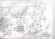
here's the real-deal, honest to goodness schematic for the unit.
i'll try and upload the rest of the doc when i can scan it.
"When the power of love overcomes the love of power the world will know peace."
Slava Ukraini!
Slava Ukraini!
- CheapPedalCollector
- Resistor Ronker
Please do.
- cspar
- Breadboard Brother
There's quite a few interesting things going on in this schematic.
The cd4049 doesn't have a V+ connection at pin 14. Instead each of the inverters is supplied to a VC+.
Also there's how the 741's collectively have a 10k resistance between ground.
I don't recall ever seeing an op amp not going directly to ground from it's "ground pin" before.
I'm supposing that the 10k resistance on the 741's ground plays into the 2n4126's current/resistance swing.
And the way the 2n4126 is set up as a variable resistor seems novel, at least to my novice eyes.
Here's a link of an original unit's gutshots with a lower parts count, where seemingly all the 741's are just replaced with mc1458's.
https://tonemachines.blogspot.com/2011/ ... r.html?m=1
"There is discussion, brainstorming, disagreement, testing, verified layout and schematic. We are the fucking stompbox university -- only for those who still read though..." - Modman
- Nocentelli
- Tube Twister
Information
- Posts: 2222
- Joined: 09 Apr 2009, 07:06
- Location: Leeds, UK
- Has thanked: 1155 times
- Been thanked: 954 times
Is that a 5.6v zener in the vref section? Hard to read, but looks like 1N5232?
No idea what's going on with the 4069
It looks more like the "negative sign in a circle" symbol is "ground" (it is also connected to the guitar input shield) and the "ground/three diminishing horizontal lines" symbol represents a vref generated from the midpoint of the 10k and zener strung between the power rails: This vref is also used to bias the input opamp. In this context, the 741 opamps are referenced to ground/zero volts through pin four as usual.
No idea what's going on with the 4069
modman wrote: ↑ Let's hope it's not a hit, because soldering up the same pedal everyday, is a sad life. It's that same ole devilish double bind again...
- Manfred
- Tube Twister
Information
- Posts: 1945
- Joined: 04 Apr 2009, 23:42
- Has thanked: 1675 times
- Been thanked: 1360 times
And the way the 2n4126 is set up as a variable resistor seems novel, at least to my novice eyes.
This circuit with the 2N4126 is the mixing stage for dry and wet signal with fixed mixing ratio von 1:1.
- aion
- Solder Soldier
Information
I can verify that the factory schematic is correct to actual units - here's the trace I did in December:
Some of their drawing choices are odd, e.g. using the ground symbol for Vref (which is virtual ground, but I've seen zero other schematics use this convention) and calling true ground the negative supply - but once you get past that it's identical. The only difference I see is the 330R resistor in series with the supply when an external adapter is used - it was 100R on the one I traced.
Here's some technical discussion - Jimi also posted the schematic in the DIYSB thread, but just to cross-link it for others who may not have seen it:
https://www.diystompboxes.com/smfforum/ ... c=126099.0
Would love to see the full service manual once you get a chance!
- cspar
- Breadboard Brother
Thanks for the insight Nocentelli. I hadn't noticed the sleeve connections.
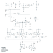
Yeah, seems that the cd4049 has Vref on it's ground pin, a different bias V that goes to the inverters and no connection to the typical + power rail.
Manfred wrote: ↑13 Aug 2021, 08:48OK, I didn't recognize it as such since the way that ground is notated at first glance it seems to have no connection to a V source.the 2N4126 is the mixing stage for dry and wet signal with fixed mixing ratio von 1:1.
With Nocentelli's insight I now see that the emitter is connected to Vref instead of it going to ground.
I was thinking that I'd hold off on this until I got a 2n4126 but since it's just a mixing stage then I'm going to go ahead and breadboard it with a sub for the 2n4126 and 1n5232 and see how that goes.
"There is discussion, brainstorming, disagreement, testing, verified layout and schematic. We are the fucking stompbox university -- only for those who still read though..." - Modman
- Nocentelli
- Tube Twister
Information
- Posts: 2222
- Joined: 09 Apr 2009, 07:06
- Location: Leeds, UK
- Has thanked: 1155 times
- Been thanked: 954 times
In some ways it would make more sense to use an opamp for that final mixer, if you use quads and dual opamps rather than seven 741s, there is a spare one left over., e.g. dual for input and out buffer, second dual for the LFO (e.g. TL062) and a quad like a LM348 for the phase stages. My breadboard is a bit small, old and worn out, so i'm going to wait until i have a new one before trying this out.
modman wrote: ↑ Let's hope it's not a hit, because soldering up the same pedal everyday, is a sad life. It's that same ole devilish double bind again...
- CheapPedalCollector
- Resistor Ronker
Interesting variant on the classic Phase 90 type phaser, it would be super easy to make a clone switchable between 2/4/6 stage and add a feedback and depth control. I bet it would sound great.
- ppluis0
- Diode Debunker
Hi Nocentelli,
There is the internal diagram of each one of the six inverters:
The designer of this pedal employs four sections using only the N-channel FET's that appear connected to ground. The P-channel were left floating as the chip isn't tied to VDD.
The four inputs wired in parallel are biased by a trimpot through a 2 Meg resistor to the point to put the lower fet's into a slight conduction.
Also at those 4 inputs are applied the low freq modulation from a triangular oscillator so the bias must be "centered" by ear to obtain the desired effect.
The advantage to use N-channel FET's from the same Cmos chip is due the fact that they are inherently matched as were manufactured at the same time in the same silicon wafer.
This contrast with the usual implementation to use discrete Jfet or LDR's that must be selected previously to have same characteristic.
BTW, what happens if we use entirely the inverters (lower Fet's) from a 4069 to make a six stage phaser ?
Had six stage phasers any advantage ?
Cheers,
Jose
- Manfred
- Tube Twister
Information
- Posts: 1945
- Joined: 04 Apr 2009, 23:42
- Has thanked: 1675 times
- Been thanked: 1360 times
I borrowed the output characteristics for the CD4069 inverter from the data sheet of the CD4007, this is not shown in the data sheet of the CD4069.
I assume that the ohmic region of the MOSFETs is used in the circuit.
The resistance value changes there along the characteristic curve depending on the operating point setting.
This operating point is changed with the modulated DC output voltage of the oscillator around the fixed DC operating point.
The resistance value changes with the oscillator frequency.
As an example, I drew a resistance characteristic into the source characteristic, which also applies to the sink characteristic to the right.
- JiM
- Diode Debunker
Information
- Posts: 967
- Joined: 11 Mar 2008, 22:56
- Completed builds: Completed builds :
Proco Rat
MXR MicroAmp in a volume pedal
TubeDriver (w/ NoS russian tube and big muff tone contol) + Phase 45 (w/ univibe cap ratio)
Dallas Rangemaster (w/ noisy OC75, negative ground)
SubCaster tube booster (w/ NoS russian tube, PtP)
Hot Harmonics
Music From Outer Space SubCommander in progress
Crackle Not OK
Simple bass blender in a 1590A
Bazz Fuss with a photo-darlington - Location: France
- Has thanked: 70 times
- Been thanked: 66 times
- Contact:
It will work.
I don't think the increased load of two more MOS gates capacitance would make a difference for the LFO.
It will have three notches in the frequency response, compared to two for 4-stages.
A tiny bit more flange-y, depending on the choice of caps (spacing of the notches).
I only give negative feedback.
- pinkjimiphoton
- Transistor Tuner
Information
- Posts: 1242
- Joined: 12 Sep 2010, 19:03
- my favorite amplifier: my own, a redesigned princeton
- Completed builds: so fucking many goddamn pedals it would make your ass hurt just looking at 'em all!!!!!
there's videos that totally suck of about 90 of 'em here:
http://youtube.com/666pinkster
gimme a like: http://facebook.com/pinkjimiphotonrocks - Location: new world order land (formerly la-la land)
- Has thanked: 358 times
- Been thanked: 480 times
- Contact:
bear with me bros, i will try and get this scanned maybe tomorrow. life's been freakishly complex and busy lately.
"When the power of love overcomes the love of power the world will know peace."
Slava Ukraini!
Slava Ukraini!
- Manfred
- Tube Twister
Information
- Posts: 1945
- Joined: 04 Apr 2009, 23:42
- Has thanked: 1675 times
- Been thanked: 1360 times
Hi Jose,
you could add the two stages and make them switchable with a rotary switch.
With two more stages the phase shift is larger, I guess this will be audible.
you could add the two stages and make them switchable with a rotary switch.
With two more stages the phase shift is larger, I guess this will be audible.
- gigelmargel
- Resistor Ronker
Very interesting phaser, which reminds me of EHX Badstone
Unfortunately, I can't find any demo on Internet. Anyone has a demo?
- ppluis0
- Diode Debunker
Thank you Manfred for your idea.
A big snowfall was announced for the next few days in my city so, if I will have to stay inside my house, it will be a good time to test this diagram on the breadboard
Cheers,
Jose
- ppluis0
- Diode Debunker
Hi there,
Found this diagram in the web scanned from a 1976 National Semiconductor audio manual.
In the description of this unit explain that the condenser values of each stage are selected to spacing one octave apart, but in several phaser diagrams I've seen all the condensers in all the stages are of equal value. (Exception are the condensers of Uni Vibe...)
Cheers,
Jose
- george giblet
- Resistor Ronker
The unequal caps makes the phasing sound slightly weaker. The notch positions become wider spread and the underlying pitch shift/vibrato is weaker. Octave spacing seem like a good mathematical foundation but in practice it is merely a specific example of spreading the cap values. If you spread the caps to some arbitrary value like 0.7234 octaves the phasing effect would a bit stronger than the octave spacing.
The Ross Phaser used one of those monolithic JFET devices but uses equal caps.,
http://home-wrecker.com/ross3.html
The Ross Phaser used one of those monolithic JFET devices but uses equal caps.,
http://home-wrecker.com/ross3.html
- mictester
- Old Solderhand
Information
My version of this circuit uses a slightly better oscillator, using an LM13600, so that I can get a nicer sweep "shape" - the simple "Miller Integrator & Comparator" triangle-wave oscillator tends to produce a sawtooth waveform at any frequency other than its "sweet spot". My oscillator gives an asymmetric sine(ish) shape and sounds much more "musical", as the sweep curve is closer to "exponential".
Using the (unbuffered) 4069UBE is slightly risky, as the internal FETs are highly vulnerable to static - it's very easy to fry the chip before installation unless you very carefully employ anti-static precautions. I tend to use a 4007UBE, as the FETs seem much more robust, and I can also use the same type of IC for the bypass (look at the Pearl effects for the bypass method).
I've tried using the same capacitor all the way through for the all-pass filters (usually 47n), and I've tried "Univibe" values, with the filter centre frequencies either harmonically or non-harmonically related. Each set of capacitors has a different "sound" - it's well worth experimenting until you find a combination that works best for your ears!
"Why is it humming?" "Because it doesn't know the words!"
- pinkjimiphoton
- Transistor Tuner
Information
- Posts: 1242
- Joined: 12 Sep 2010, 19:03
- my favorite amplifier: my own, a redesigned princeton
- Completed builds: so fucking many goddamn pedals it would make your ass hurt just looking at 'em all!!!!!
there's videos that totally suck of about 90 of 'em here:
http://youtube.com/666pinkster
gimme a like: http://facebook.com/pinkjimiphotonrocks - Location: new world order land (formerly la-la land)
- Has thanked: 358 times
- Been thanked: 480 times
- Contact:
dammit chris, you know i still love you maaaaannnnnnnn
i gotta remember to scan and upload the rest of the doc for posterity's sake.
would LOVE to see your version of this beast, i bet it smokes this thing.
i hardly ever get to diy shit anymore, full time solder monkey these days which i pretty much hate
but psyched to see ya still doing this stuff too, mate.
peace n chicken grease from 'cross the pond
"When the power of love overcomes the love of power the world will know peace."
Slava Ukraini!
Slava Ukraini!