
Its the same as above, just with the battery clips reversed.phibes wrote:Post pictures of your wiring again. Sounds like your groundings still off since the attack knob didn't work.
Marshall - Supa Fuzz (196x) [gut shot picture thread]

-
Volume11

- Breadboard Brother
Information
- Posts: 54
- Joined: 18 Jan 2010, 01:24
- my favorite amplifier: Silvertone 1484
Sunn 2000s(bass) - Location: Houston TX
- Contact:
Hey guys, I built this pedal from this vero layout, but its not working. no sound what so ever. I measured the transistors at 9.2v (all 3 of them at all 9 connections). Should they measure closer to 4.5v???Electric Warrior wrote:Here you go:
Note that it was designed with .15" pitch vero in mind.

-
Electric Warrior

- Diode Debunker
there's something seriously wrong with your build. Q1's and Q2's emitters go to ground. They have to measure 0V... The other readings are off as well.
-
Electric Warrior
- Diode Debunker
even if he missed the track cuts the the emitter voltages should measure 0V, no?
-
Volume11
- Breadboard Brother
Information
- Posts: 54
- Joined: 18 Jan 2010, 01:24
- my favorite amplifier: Silvertone 1484
Sunn 2000s(bass) - Location: Houston TX
- Contact:
Thanks for the quick replys... I'll check my traces and cuts when I get home from work, and I'll get back to you guys. I'll try to post some pics aswell
-
Volume11
- Breadboard Brother
Information
- Posts: 54
- Joined: 18 Jan 2010, 01:24
- my favorite amplifier: Silvertone 1484
Sunn 2000s(bass) - Location: Houston TX
- Contact:
So... I didn't have the ground trace grounded to the rest of the circuit. It works now but, it's really noisy. Is that normal for this build?
-
Electric Warrior
- Diode Debunker
It totally depends on your transistor selection. You might want to socket them first to try out what combination of gains/leakages works best for you.
-
Electric Warrior
- Diode Debunker
wrong thread 
-
Rolbista
- Solder Soldier
I made a Supafuzz enclosure from sheet stainless steel. Dimensions and shape are approximate, I couldn't find any info on that. In fact, i didn't even know what to type into google...  Looks like this:
- Attachments
-
-
- cimg5107.jpeg (27.31 KiB) Viewed 2988 times
-
- img_0341.jpeg (31.82 KiB) Viewed 2988 times
-
John Lyons

- Solder Soldier
Very Nice!
.
.
.
-
Rolbista
- Solder Soldier
-
Nyquist5

- Breadboard Brother
Information
Hey there,
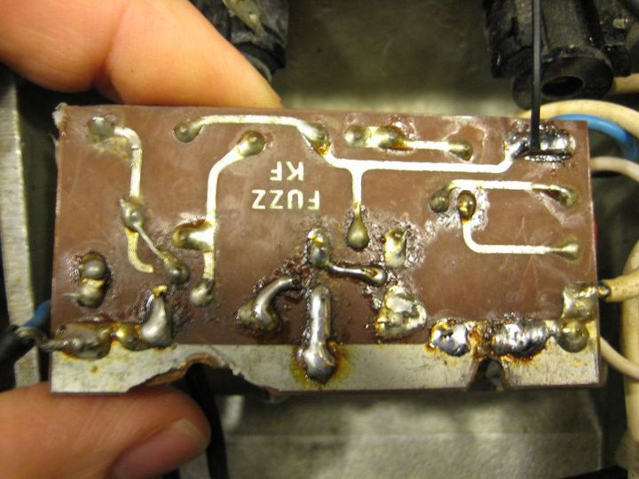
Nothing that isn't known about this SupaFuzz, but it uses AC126 so I thought I'd share the guts with you. One Electroytic cap does not seem original and the pots have been changed. It has been well used and abused. Apart from that, it seems stock. The sound is pretty mushy due to failing electrolytic caps but the owner wanted to keep them in.


Nothing that isn't known about this SupaFuzz, but it uses AC126 so I thought I'd share the guts with you. One Electroytic cap does not seem original and the pots have been changed. It has been well used and abused. Apart from that, it seems stock. The sound is pretty mushy due to failing electrolytic caps but the owner wanted to keep them in.
-
Electric Warrior
- Diode Debunker
Wow, that looks bad. Whoever swapped the transitors and electrolytics (I think all of them are probaby replacements) must have done it with a blowtorch 
-
Nyquist5
- Breadboard Brother
Information
Yes, this pedal has been through rough times. The board is damaged and pretty much every single screw has been lost and replaced with an inappropriate one. And a Boss PSU was hardwired to the board, through a hole drilled in the front of the casing...  Talk about throwing money out of the window.
Even though the board shows some botched resoldering, I don't believe that the transistors have been replaced. Likewise, only one electrolytic has been replaced: from my experience, the other two definetly are contemporary of the pedal.
Even though the board shows some botched resoldering, I don't believe that the transistors have been replaced. Likewise, only one electrolytic has been replaced: from my experience, the other two definetly are contemporary of the pedal.
-
Electric Warrior
- Diode Debunker
You mean the Erie electrolytic on the right? That one's contemporary to the pedal. I think Marshall even used that type in some amps.
In fact all the components appear to be from the right period, but I haven't seen any other Supa Fuzz with that exact types of electrolytics and transistors yet. Doesn't need to mean much, my collection of Supa Fuzz gut shots is somewhat limited, but on the other hand every single solder joint that belongs to a transistor or electrolytic looks like it's been badly messed with.
This is the closest match I can find in my database. All resistor types are identical: