Does anyone have a schematic for this thing? Or could someone verify a layout? I have a layout done by MoreCowbell a while back that's a trace of an original unit. But I wanted to do one that would fit in a 1590b.
After giving the "exact clone" layout a closer look, I noticed it has a lot in common with the DOD 250/Distortion + circuit. So I hacked apart a couple of Markm's layouts, and came up with something that looks like *should* work. I can't find a schem for it though.
I also thought I'd get permission from Mark and Andy before posting their hacked up, and original layout work, respectively. This is also my first go at any sort of PCB layout work. If there's any interest, I'll post it.
DeArmond - Square Wave Distortion Generator [schematic]
-
Bernardduur

- Transistor Tuner
The schematic was already posted somewhere; I now used it for a long time and still love it!
'No more....... loud music.......'
Follow my love for pedals and amps on https://bernardduur.blogspot.com and https://www.instagram.com/bernardduur1
Follow my love for pedals and amps on https://bernardduur.blogspot.com and https://www.instagram.com/bernardduur1
Found the schem. I don't know why it took me so long to find it. Anyway...

And my attempt:
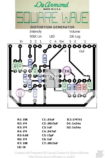
According to the schem, R5 on my layout should be 5.6k.
"LR" is for the LED. LED cathode to solder pad "C" anode to "A" and run a wire from "SW" to the stomp switch.
I'll wait for proofreading before I post a transfer. Plus I have to go watch Evil Dead, and I need to "sweeten up" the transfer image.
And my attempt:
According to the schem, R5 on my layout should be 5.6k.
"LR" is for the LED. LED cathode to solder pad "C" anode to "A" and run a wire from "SW" to the stomp switch.
I'll wait for proofreading before I post a transfer. Plus I have to go watch Evil Dead, and I need to "sweeten up" the transfer image.
-
RnFR
- Old Solderhand
Information
guts-
- Attachments
-
- Dearmond Square Wave Generator
- DeArmondSWG.jpg (431.67 KiB) Viewed 5964 times
"You've converted me to Cubic thinking. Where do I sign up for the newsletter? I need to learn more about how I can break free from ONEism Death Math." - Soulsonic
Blog-APOCALYPSE AUDIO
Blog-APOCALYPSE AUDIO
-
rhandy gaye

- Solder Soldier
i noticed that too, almost exact same layout.
gut shots of brown sound at tcgakki
gut shots of brown sound at tcgakki
-
rhandy gaye
- Solder Soldier
yep, that's the pick.

Information
- Posts: 22
- Joined: 03 Feb 2010, 10:47
- my favorite amplifier: Vox AC-30
- Completed builds: Sola Sound Tone Bender MKI 1965, Electro-Harmonix Pulsar, Mu-Tron III, Lovetone Meatball, Wolly Mammoth.
Mods: Small Stone (Frankestone), Rat (Tri-diode switch plus resistors, caps and CI mod), Dunlop Cry Baby (Caps and resistors). - Location: London, U.K
Hi guys,
I saw that pic (RnFR) at google many times and the above circuit/PCB (Burglar) but I also saw this photo book:
https://s123.photobucket.com/albums/o29 ... 0Generator
but the values of the capacitors are hidden in every pic that I saw, so how acurate could be the values that everybody has from google pics and so? Anyone here have pics where you be able to read the capacitors' values??
Thanks a lot guys!
-
Dan N

- Resistor Ronker
The schematic posted above was done by AG. No reason in the world not to totally trust it. The values were not guessed at, I looked at my unit and communicated the values to Gottfried.
This one:
http://members.fortunecity.com/uzzfay/dsw/sqwave.html
I never got the diode #'s before I sold it, but they are Ge. I can't remember about the pots, but assume that the values are correct and that the tapers were left uncertain.
I'm a fuzz guy so this pedal did not live with me very long.
This one:
http://members.fortunecity.com/uzzfay/dsw/sqwave.html
I never got the diode #'s before I sold it, but they are Ge. I can't remember about the pots, but assume that the values are correct and that the tapers were left uncertain.
I'm a fuzz guy so this pedal did not live with me very long.
Dick joke has expired.
Information
- Posts: 1
- Joined: 05 May 2010, 03:15
this was my first real dirt pedal. I regret selling it a few years back. I have always wanted a clone of it so see if i would still like the pedal or if im just holding on to the good memories.
I got some pics i can share with anyone if you are interested.
I got some pics i can share with anyone if you are interested.
I have a 1977 DeArmond Square Wave op-amp distortion pedal. I prefer the low distortion settings. Going into an already distorted amp, this gives just a bit more bite in a very neutral way.
However, in recent times the output in this low output level use is very low. Could it be the IC? I have an NTE941M - 971E chip. Most Square Waves have LM741CN chips installed (see here). I had one. And the one with the NTE941M sounds way better to my ears.
Other culprits could be the capacitors. I am a lay person. But I can solder...
Thanks
Ulrich
-
ppluis0

- Diode Debunker
Hi Ulrich and welcome to this forum.
You can remove the IC and install an 8 pin socket:
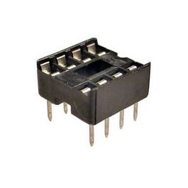
This way you can swap among several single op amps (741, LM308, LM301, TL071 and so on) and see what adapt better to your preferences.
Cheers,
Jose
You can remove the IC and install an 8 pin socket:
This way you can swap among several single op amps (741, LM308, LM301, TL071 and so on) and see what adapt better to your preferences.
Cheers,
Jose
-
modman

- a d m i n
Information
- Posts: 4898
- Joined: 19 Jun 2007, 16:57
- Has thanked: 4411 times
- Been thanked: 2139 times
Hi Ulrich, while you are at it, could you let us know the values of the potmeters in your unit. They are still missing from above schematic. Also, the diode have not been identified yet. Would be great if you could share some pictures and clear this matter...Tulrich wrote: ↑03 Jan 2022, 15:37 I have a 1977 DeArmond Square Wave op-amp distortion pedal. I prefer the low distortion settings. Going into an already distorted amp, this gives just a bit more bite in a very neutral way.
However, in recent times the output in this low output level use is very low. Could it be the IC? I have an NTE941M - 971E chip. Most Square Waves have LM741CN chips installed (see here). I had one. And the one with the NTE941M sounds way better to my ears.
Other culprits could be the capacitors. I am a lay person. But I can solder...
Thanks
Ulrich
Please, support freestompboxes.org on Patreon for just 1 pcb per year! Or donate directly through PayPal
On the pots I read: On the intensity knob 1377726 (CTS 1977) and 229 - 00471 - 00. I measure between left and middle lug (to ground, right lug is free) 513k.
Output pot: CTS... CF 1100. I measure (between left and middle lug, right lug to ground) 0 - 3,9k, but then it is going down again to 2,84 k. Is there something wrong with the pot? And this causes the problem of a low output?
On the diodes (without desoldering them) I can read IN 87 A ITT. I think both are the same.
You find a picture of board here:
I also added a picture of the Square Wave I have already sold:


I have ordered a new NTE941. Should I get a new pot? 5K? Or clean the pot?
Thanks
Ulrich
Output pot: CTS... CF 1100. I measure (between left and middle lug, right lug to ground) 0 - 3,9k, but then it is going down again to 2,84 k. Is there something wrong with the pot? And this causes the problem of a low output?
On the diodes (without desoldering them) I can read IN 87 A ITT. I think both are the same.
You find a picture of board here:
I also added a picture of the Square Wave I have already sold:
I have ordered a new NTE941. Should I get a new pot? 5K? Or clean the pot?
Thanks
Ulrich
-
modman
- a d m i n
Information
- Posts: 4898
- Joined: 19 Jun 2007, 16:57
- Has thanked: 4411 times
- Been thanked: 2139 times
Thanks so much for the pictures! Feel free to attach them... so many threads have become unreadable because of dead links to external pictures...
Better to measure the pot between the outer lugs... above layout suggests a 10k pot. However, fluctuating resistance between outer lug and wiper is not a good sign... Spraying some contact cleaner in and working the pot is a first step...
Maybe a good idea if you do replace the chip, to solder in a socket... as Jose already suggested. I tend to think the chip is not the problem...
Do keep us posted.
Please, support freestompboxes.org on Patreon for just 1 pcb per year! Or donate directly through PayPal
I also ordered a socket. I will spray the pot.
I just found how to attach files.
I measured the pots again, now both between the outer lugs. The output pot is 2.93k. The intensity pot is 513M.
I just found how to attach files.
I measured the pots again, now both between the outer lugs. The output pot is 2.93k. The intensity pot is 513M.
- Attachments
-
-
-
-
modman
- a d m i n
Information
- Posts: 4898
- Joined: 19 Jun 2007, 16:57
- Has thanked: 4411 times
- Been thanked: 2139 times
Time to desolder the pot and measure again to be sure...
Let's hope the intensity pot is about 500k
If you care about performance of the unit, perhaps replacing the electrolytics on this 40+ year old pedal may be an improvement too.
Diodes must be 1N87A then... but there are different types
- 1N87A datasheet
Please, support freestompboxes.org on Patreon for just 1 pcb per year! Or donate directly through PayPal
-
ppluis0
- Diode Debunker
Hi folks,
This stompbox is in all aspects equal to MXR Distortion+, so the following link explain how this design works if someone here don't knew that already
https://www.electrosmash.com/mxr-distor ... s-analysis
Cheers,
Jose
This stompbox is in all aspects equal to MXR Distortion+, so the following link explain how this design works if someone here don't knew that already
https://www.electrosmash.com/mxr-distor ... s-analysis
Cheers,
Jose