Elk - Twin Amp 50 repair  [schematic]

Tube or solid-state, this section goes to eleven!
User avatar
pandadandan
Breadboard Brother
Information
Posts: 116
Joined: 09 Oct 2007, 06:12
Location: Tokyo, Japan
Has thanked: 7 times
Been thanked: 5 times

Post by pandadandan »

I bought this from an auction site in Japan on a whim the other night for $100. I thought something along the lines of "If it doesn't work, it'll make a great introduction to the world of amp repair."

Upon receiving it, I checked to see if the tubes were seated properly, then powered it up in standby (no input, connected to a cab). The amp hummed to life and the tubes lit up. The tubes are beautiful Matsushita ones (their factory was set up by Phillips/Mullard I believe) and they glowed nicely. After a few minutes wait, I took it out of standby. BZZZZZZZZZZZzzzzzzzzzZZZZZZZZZZzzzzzzzzz. The sound from the amp was almost as depressing as seeing one of the 6CA7 slowly redplate. I shut off the amp and went to work.

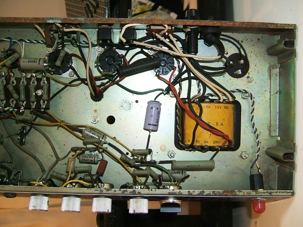
Upon returning, I took the chassis out and took a bunch of photos:
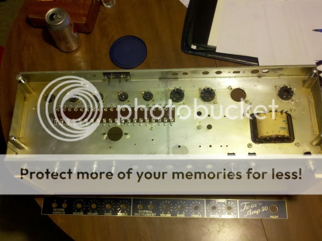
Wide chassis shots:
Image
Image

One of the close-ups:
Image
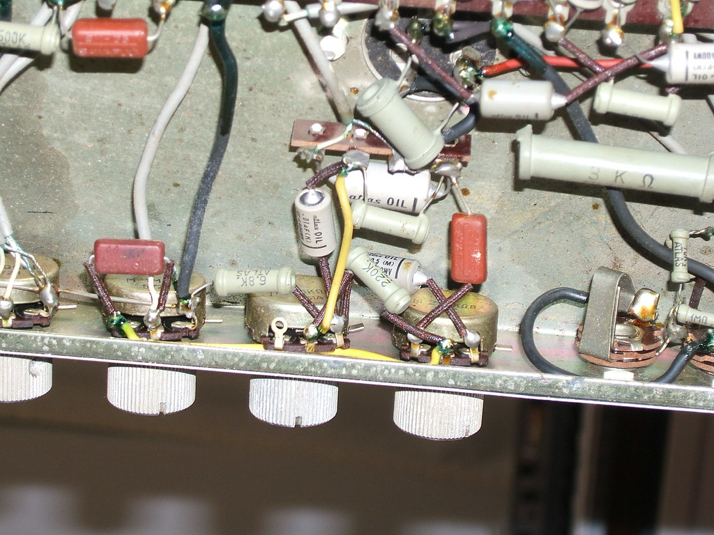
Green solder joints?!?!?!

Here's the link to the rest and a schematic I found.
http://www.flickr.com/photos/36530055@N ... 540141989/


Sooooooooooo...
Redplating tube, craploads of buzz, horrendous crackles and pops when turning any knobs...
Possible to tackle as a first-ever amp repair? It's pretty fucking intimidating. I was expecting the filter caps to be all neatly put together, but they seem to be stuck in various places.

Your advice would be GREATLY appreciated.
3367839911_b92a38f584_o.gif

User avatar
RnFR
Old Solderhand
Information
Posts: 4879
Joined: 09 Jan 2008, 06:02
my favorite amplifier: Traynor YBA-III, Fender Super Six
Completed builds: custom fuzz.
Location: Inner Earth
Has thanked: 139 times
Been thanked: 133 times
Contact:

Post by RnFR »

i would replace all of those electrolytics. i pulled some just like it out of an old radio, and they were crazy leaky.
"You've converted me to Cubic thinking. Where do I sign up for the newsletter? I need to learn more about how I can break free from ONEism Death Math." - Soulsonic

Blog-APOCALYPSE AUDIO

User avatar
DougH
Transistor Tuner
Information
Posts: 1087
Joined: 18 Aug 2007, 04:53
Has thanked: 4 times
Been thanked: 23 times

Post by DougH »

Also, replace the tubes with known good ones.
"You have just tubescreamered or fuzzfaced yourself " -polarbearfx

User avatar
KindaFuzzy
Degoop Doctor
Information
Posts: 643
Joined: 10 Nov 2008, 14:00
Location: Canada
Has thanked: 79 times
Been thanked: 257 times

Post by KindaFuzzy »

I love fixing stuff like this. First thing, like everyone else said, replace all electrolytics, including bias supply and cathode bypass ones. Second, I don't care for the way the standby switch is wired, or how it looks like there's no bias for the tubes while on standby, that could easily be changed to the Marshall/Fender style with an adjustable bias. After you do all this turn the amp on with no tubes in and check to see that there's actually negative voltage on both pin 5's for the el34 tubes. I fixed a silverface Fender twin that someone had stuck a 35v filter cap in the bias supply that was leaking, and caused an output tube to die.

The output tubes most likely need be replaced too like DougH said. And what a goofy phase inverter setup with half a 6aq8, and half a 12ax7 in a long tailed pair. 12ax7 driving the reverb tank too instead of a 12at7, weird.

I like this website for all that kind of info: http://www.freewebs.com/valvewizard/index.html

User avatar
tictac
Breadboard Brother
Information
Posts: 149
Joined: 27 Nov 2008, 07:30
Been thanked: 10 times

Post by tictac »

Well that was wierd :scratch: I just wrote a post for you about how to do a recap and it didnt show up when I hit submit... :evil:

One thing I noticed is there's a 100mfd cap after the GZ34 rectifier. This value is too big, you may have a bad/weak rectifier. 60mfd is supposed to be the max value, I'd replace with 40mfd. (two 20mfd in parallel) and make sure to observe correct polarity for the -bias filter cap. A common newbie mistake is putting that cap in backwards and having it blow up in your face :o Not Good!

Also I'd replace the wire that goes from pin8 to ground on the octal power tube sockets with a 1 ohm resistor to ground. Clip a DMM set to millivolts across this resistor and you can read the milliamps per tube current draw. If you really are getting 450V B+ one the plates as per the schematic then 36 to 39ma per tube is just right :thumbsup

You'll probably need to play with the value of R63 to get it in that range. Smaller resistor=higher current; Bigger resistor=lower current...

Have Fun

TT

User avatar
Spewbag
Breadboard Brother
Information
Posts: 123
Joined: 09 Jul 2007, 13:47
Been thanked: 1 time

Post by Spewbag »

http://www.tubesandmore.com/

First thing you need to get is some Iso alcohol and clean those tube sockets. Go to the link above and order some De-oxit and use that in the pots to lube and clean them as well as the input and speaker jacks, Replace all the E caps and then touch up all the solder joints and make sure chassis grounds are securely soldered.

User avatar
pandadandan
Breadboard Brother
Information
Posts: 116
Joined: 09 Oct 2007, 06:12
Location: Tokyo, Japan
Has thanked: 7 times
Been thanked: 5 times

Post by pandadandan »

Thank you all so much.
I've ordered some deoxit and a bunch of replacement capacitors. I'm totally new to these things (modding an SD-1 doesn't seem to compare somehow :lol: ), so all your advice is greatly, GREATLY appreciated.

:hug:

I like this place.

User avatar
pandadandan
Breadboard Brother
Information
Posts: 116
Joined: 09 Oct 2007, 06:12
Location: Tokyo, Japan
Has thanked: 7 times
Been thanked: 5 times

Post by pandadandan »

tictac wrote:Well that was wierd :scratch: I just wrote a post for you about how to do a recap and it didnt show up when I hit submit... :evil:

One thing I noticed is there's a 100mfd cap after the GZ34 rectifier. This value is too big, you may have a bad/weak rectifier. 60mfd is supposed to be the max value, I'd replace with 40mfd. (two 20mfd in parallel) and make sure to observe correct polarity for the -bias filter cap. A common newbie mistake is putting that cap in backwards and having it blow up in your face :o Not Good!

Also I'd replace the wire that goes from pin8 to ground on the octal power tube sockets with a 1 ohm resistor to ground. Clip a DMM set to millivolts across this resistor and you can read the milliamps per tube current draw. If you really are getting 450V B+ one the plates as per the schematic then 36 to 39ma per tube is just right :thumbsup

You'll probably need to play with the value of R63 to get it in that range. Smaller resistor=higher current; Bigger resistor=lower current...

Have Fun

TT
Dear TicTac,
Thanks for the long message. The two can caps are both 50uF/50uF. That schematic seems to be a bit off in terms of values, as there's a bunch of caps in this thing (cathode bypass caps?) that are 30uF which in the schematics are 33/50uF.

Am I correct in understanding that the can cap following the rectifier (connecting to the center tap of the OT??) should be a 20uF/20uF replacement instead of 50/50?

As far as recapping goes, I understand replacing the filter caps and the -bias filter cap. Should I replace all the caps? These oil caps are out of my realm of understanding, but they do look rather ancient. I don't mind overhauling a lot as it's more of a fun learning project than anything.

Thanks for your time.

User avatar
tictac
Breadboard Brother
Information
Posts: 149
Joined: 27 Nov 2008, 07:30
Been thanked: 10 times

Post by tictac »

Are the two sections of the 50/50 cap connected? If so thats 100 mfd and you will want to replace with a two section 20/20 mfd or you could replace with another 50/50 mfd and use Each 50 mfd section seperately. E.I. one 50 mfd section for the 1st filter (plate) and the other 50 mfd for the 2nd (screen) filter.

TT

User avatar
pandadandan
Breadboard Brother
Information
Posts: 116
Joined: 09 Oct 2007, 06:12
Location: Tokyo, Japan
Has thanked: 7 times
Been thanked: 5 times

Post by pandadandan »

tictac wrote:Are the two sections of the 50/50 cap connected? If so thats 100 mfd and you will want to replace with a two section 20/20 mfd or you could replace with another 50/50 mfd and use Each 50 mfd section seperately. E.I. one 50 mfd section for the 1st filter (plate) and the other 50 mfd for the 2nd (screen) filter.

TT
Image
The base of the first can is visible in the top right (right click the image and click "view" to see the entire picture). It seems to be connected separately for each section. I can't see the connecting r68 resistor in the photos, though I'll double-check tonight.

Thanks a lot for your help. I'm looking forward to a world of frustration and swearing at walls before I get to enjoy any kind of sound from the amp :D

User avatar
dorrisant
Information
Posts: 31
Joined: 08 Sep 2010, 14:48
Has thanked: 53 times
Been thanked: 5 times

Post by dorrisant »

The thread just stops... Did you ever get this thing up and running?

User avatar
dorrisant
Information
Posts: 31
Joined: 08 Sep 2010, 14:48
Has thanked: 53 times
Been thanked: 5 times

Post by dorrisant »

I have one of these amps and i have thought about turning it into something else... like a Rocket with reverb. Does anyone have any info or experience with this amp? Mine does not work... doesn't redplate though. I am wondering if it is worth resurrecting or might be better served as a platform for something better...? Does anyone know the output transformer input impedance? Just wondering what I could do with it... Lots of good wire-wound resistors... maybe better off using them out of the signal path. Mine looks exactly like the pics from above. If anyone wants to discuss it further then please do.
Tony

User avatar
jrjoe21
Information
Posts: 41
Joined: 03 Jan 2008, 16:03
my favorite amplifier: DIY Chieftain-R66 clone
Completed builds: Many
Location: Montreal
Has thanked: 26 times
Been thanked: 3 times
Contact:

Post by jrjoe21 »

I have one... Did not sound that great stock...mine worked (except the trem) when I got it (50$) including the cab... The reverb was pretty crappy.

I ended it up converting it to something totally different (replaced all parts except the transformers/chassis). The amp is now a mix between a Route 66/Chieftain and it really does sound great...

Pre chan 1 - Chieftain (Vol/bass/mid/treble) - 12ax7
Pre chan 2 - Route66 (Vol/bass/treble) - ef86
PI - Chieftain (cut/Master Vol) - 12 ax7
Output - Chieftain - el34... probably changed the cathode Rx value... can't remember
Power Supply - added a choke / Recapped with JJ 50/50
Speakers - I replaced the stock speakers (1 ceramic/ 1 alnico) for Red Fangs

I can dig out pictures and the schematics I used and record some audio clips, if somebody would like that.

It's my favorite amp (pretty loud, but manageable with the Master Vol). The Ef86 channel has more gain than the 12ax7 one, but they have a similar character. I use a A/B box to switch betweeen channels and a mosfet booster to heat things up.

I would do it again without hesitation...
“Happiness in intelligent people is the rarest thing I know.” - E. Hemingway

User avatar
dorrisant
Information
Posts: 31
Joined: 08 Sep 2010, 14:48
Has thanked: 53 times
Been thanked: 5 times

Post by dorrisant »

jrjoe,
Glad to see someone has an opinion about the tone of this amp. I had a e-chat with a guy a while back. His worked just fine...?... but that is subjective. He wasn't all that impressed either. I think a platform is what this one will be. Lots of parts on the chassis will defintely be recycled. I would love to see what you came up with. Please post what you have and I will post what I do as well. Kinda seems this post may be out of place in a stompbox forum... but who am I to judge... I'm glad to see someone respond to an old thread.
I'll dig up what I have and post it when I can.
Tony

User avatar
jrjoe21
Information
Posts: 41
Joined: 03 Jan 2008, 16:03
my favorite amplifier: DIY Chieftain-R66 clone
Completed builds: Many
Location: Montreal
Has thanked: 26 times
Been thanked: 3 times
Contact:

Post by jrjoe21 »

I'll scan my project doc at the office tomorrow and post them afterwards... Brings me back, I did this in 2006-2007... In the meantime, here are a couple of pics...
DCChiefStack1.JPG
I changed the grill cloth and knobs and reversed the faceplate...
DCChief1.JPG
The inners I've removed the switching board... Use an external a/b instead... this is not the final version... I always forget to take pictures once I'm done...
“Happiness in intelligent people is the rarest thing I know.” - E. Hemingway

User avatar
DrNomis
Old Solderhand
Information
Posts: 6807
Joined: 16 Jul 2009, 04:56
my favorite amplifier: Self-Built Valve Amp Head :)
Completed builds: Dallas Arbiter Fuzz Face,Tone Bender Professional Mk 3,Tone Bender 3-Knob,Baja BK Butler Tube Driver,Baja Real Tube Overdrive,Roger Mayer Octavia,EH Soul Preacher,Tech 21 XXL Distortion,MFOS Weird Sound Generator.
Location: Darwin,Northern Territory Australia
Has thanked: 98 times
Been thanked: 279 times

Post by DrNomis »

pandadandan wrote:
tictac wrote:Are the two sections of the 50/50 cap connected? If so thats 100 mfd and you will want to replace with a two section 20/20 mfd or you could replace with another 50/50 mfd and use Each 50 mfd section seperately. E.I. one 50 mfd section for the 1st filter (plate) and the other 50 mfd for the 2nd (screen) filter.

TT
Image
The base of the first can is visible in the top right (right click the image and click "view" to see the entire picture). It seems to be connected separately for each section. I can't see the connecting r68 resistor in the photos, though I'll double-check tonight.

Thanks a lot for your help. I'm looking forward to a world of frustration and swearing at walls before I get to enjoy any kind of sound from the amp :D


What I would do is re-do the mains lead so that it is held in place by a cable clamp grommet instead of just a knot,using a knot to hold the mains lead in place is no longer considered safe nowdays(it's actually illegal), since the surrounding metal can cut into the insulation and touch a live wire..... :)
Genius is not all about 99% perspiration, and 1% inspiration - sometimes the solution is staring you right in the face.-Frequencycentral.

User avatar
jrjoe21
Information
Posts: 41
Joined: 03 Jan 2008, 16:03
my favorite amplifier: DIY Chieftain-R66 clone
Completed builds: Many
Location: Montreal
Has thanked: 26 times
Been thanked: 3 times
Contact:

Post by jrjoe21 »

As discussed here are my project docs scans. Poke me if you have questions
Scan11-02-22 0741.tif
Scan11-02-22 0741.tif (342.05 KiB) Viewed 3505 times
dorrisant, really interested in your project... post progress and good luck.
“Happiness in intelligent people is the rarest thing I know.” - E. Hemingway

User avatar
dorrisant
Information
Posts: 31
Joined: 08 Sep 2010, 14:48
Has thanked: 53 times
Been thanked: 5 times

Post by dorrisant »

Got the scans... diggin it. I would probably dig it more so if you had clips posted... but I know how that goes.
I gutted mine down to the chassis and the 9 pin sockets... sanded, cleaned and reshaped (front was pushed in), I even salvaged the eyelet board and it will work just fine with the new "Rocket". I've got about half of the heater wiring done as well as the pots, jacks and switches mounted. Made an order from tube depot yesterday. I still need to order the OT and choke. I'll post pics up to this point later, but here is one about half way to the present point:

Image

Tony

User avatar
fosnal1950
Breadboard Brother
Information
Posts: 147
Joined: 16 Mar 2008, 13:41
Has thanked: 5 times

Post by fosnal1950 »

Looks very much like a Guyatone . Don't use the Atlas oil caps anymore, they're all leaky .

User avatar
jrjoe21
Information
Posts: 41
Joined: 03 Jan 2008, 16:03
my favorite amplifier: DIY Chieftain-R66 clone
Completed builds: Many
Location: Montreal
Has thanked: 26 times
Been thanked: 3 times
Contact:

Post by jrjoe21 »

a quick and dirty clip (with crappy playing)...

http://cid-e311aaba087b423b.office.live ... CChief.mp3

Recorded direct with a axetrack (too early to play louder). It sounds more chimey and less compressed when recorded with a mic through the speakers. The first 50 seconds are on the DC Chief channel, the rest is on the route66 channel.
“Happiness in intelligent people is the rarest thing I know.” - E. Hemingway

Post Reply