Hi all. I just discovered this site and joined. Amazing resource! I thought people might be interested in a stompbox I designed in the 2002 and am still using. It simulates the tone shaping of a Fender amp, so I called it the "Fenderizer". Maybe some people will find it useful:
http://www.marksmart.net/gearhack/fende ... rizer.html
Fenderizer Pedal
-
Ben N

- Cap Cooler
Much like the clean channel preamp in my Champ 25SE, except that the Champ runs on +/- 16v, has a moderately useful mid-shift switch, and you have those additional filtering stages at the end. Did those come straight from the other Fender preamps, or did you design them to achieve some specific goal? Also, do you think that boosting the operating voltage to increase headroom would be beneficial?
I just copied the filter stages right from the Stage 160 schematic. I don't totally understand what they do. LOL. I took their circuit and removed the overdrive and reverb circuits. It might be useful to boost the operating voltage, but I've never had a problem with it clipping.Ben N wrote:you have those additional filtering stages at the end. Did those come straight from the other Fender preamps, or did you design them to achieve some specific goal? Also, do you think that boosting the operating voltage to increase headroom would be beneficial?
-
Frank_NH
- Solder Soldier
I like it. You could build this with a charge pump to get +/- 9V for a little extra headroom. Also, nice to see the tone shaping downstream of the volume control. Someone could design a vero layout though I could also build this on my breadboard to check it out for myself. Thanks for posting.
-
plush

- Cap Cooler
Can anybody tell me, why is there a 27k resistor on the output? Can't find any need of that much of impedance.
I'd also add an input buffer made out of the half of 3rd opamp...
I'd also add an input buffer made out of the half of 3rd opamp...
-
Frank_NH
- Solder Soldier
I agree - you can drop the 27K resistor at the output. The input probably doesn't need a buffer but if you have an extra op amp, what the heck.plush wrote:Can anybody tell me, why is there a 27k resistor on the output? Can't find any need of that much of impedance.
I'd also add an input buffer made out of the half of 3rd opamp...
Yeah, now that I think about it that resistor is not necessary. I just blindly copied the circuit from the Fender schematic, so it's possible I included part of the input stage of the power amp without realizing it didn't need to be there. Duh.
Here is the schematic of the Stage 160 I copied the circuit from:
http://bee.mif.pg.gda.pl/ciasteczkowypo ... Manual.pdf
It doesn't have a 27.5 resistor there, so now I am wondering if I made a mistake on that schematic. Maybe I got confused about R58 and accidentally including it twice. Thanks for bringing that to my attention! I'll try to dig up my documentation.
I'll bet what I did is put the wrong value on the schematic for the value of that resistor. Maybe it's really 1K like R67 on the Stage 160 schematic. In Eagle I might have copied the 27.5K resistor from earlier in the schematic and forgotten to change its value to 1K. I made this schematic in Eagle several years AFTER building the pedal.
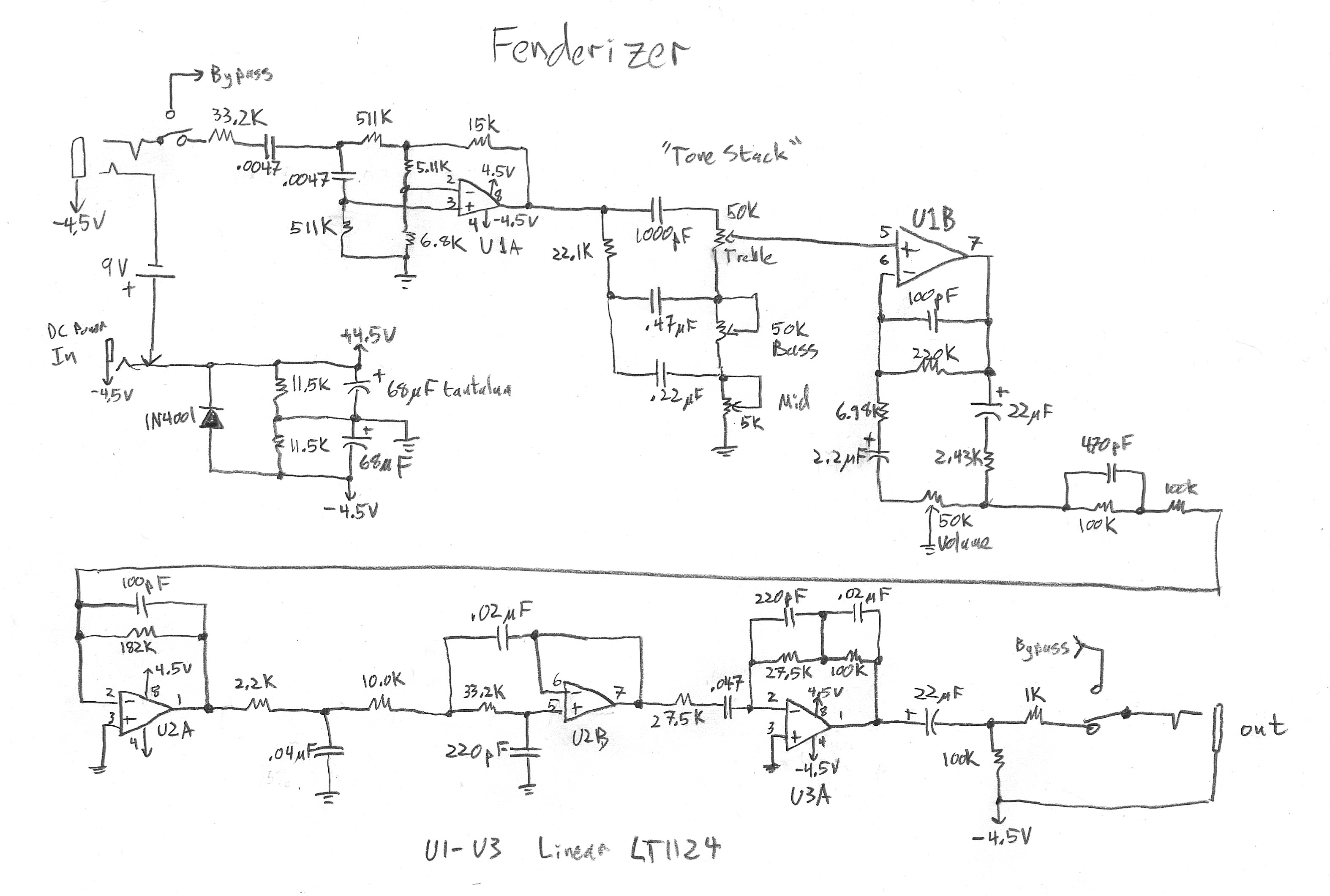
Yep, that's it. It was actually 1K. Here is a link to the original schematic I think I wired the pedal from (this was a long time ago, LOL). It was up on that web page, then I removed the link to it when I posted the nicer-looking Eagle schematic. Fortunately the old hand-drawn schematic image is still there in that directory:
http://www.marksmart.net/gearhack/fende ... ematic.JPG
So that's what's really in the pedal.
http://www.marksmart.net/gearhack/fende ... ematic.JPG
So that's what's really in the pedal.
-
phatt
- Transistor Tuner
Just a Q,
That schematic makes no sense as the ground and bias seem to be labeled wrong.
As drawn I doubt if it would work as input and output ground are labeled -4.5V
Phil.
That schematic makes no sense as the ground and bias seem to be labeled wrong.
As drawn I doubt if it would work as input and output ground are labeled -4.5V
Phil.
I draw it differently than a lot of people. I show the voltages as seen by the internal circuitry rather than as seen from the outside. That makes it easier for me to understand what's going on. What looks like -4.5 to the op-amps is the same as ground as seen from the input and output jacks.