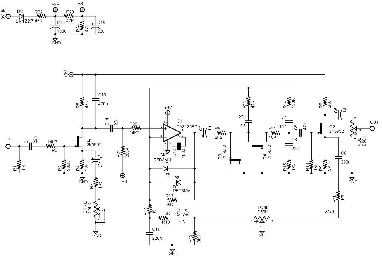
Any knowledge on regular JFETs used like "clipping diodes" in the Negative feedback loop of an opamp? Such is the first stage of the Such is the first stage of the Mad Professor Stone Grey Distortion.
https://www.freestompboxes.org/viewtopic ... ey#p193074
Not mosfets, 2n3819 jets.
They are hooked up anti-parallel like usual with DS together and gate the other side... These things don't really pass current G to S&D ( or backwards) do they?
JFETS used like clipping diodes?
-
idy

- Breadboard Brother
Information
- Posts: 126
- Joined: 14 Dec 2011, 04:41
- Completed builds: FFs, Octavias, TBMKIIIs, Buzzarounds/alikes, Axis Fuzz', CS Overdriver, BMPs, Black '65s, MOSFETODs, WiiO, RAH, Klons, AC30, DLS, TSs and many variants, Small Clones, UniVibes, E. Mistress, Mutron Env Filter, Ross/Dynacomps,, EA Trems, TremLunes, Katana Boosters, BYOC Tri Boosters, other boosters and buffers, PT2399 delays, SKRM based delays, Belton Brick Reverbs, 3band parametric EQ,
- Location: Idyllwild, CA
- Has thanked: 27 times
- Been thanked: 31 times
-
idy
- Breadboard Brother
Information
- Posts: 126
- Joined: 14 Dec 2011, 04:41
- Completed builds: FFs, Octavias, TBMKIIIs, Buzzarounds/alikes, Axis Fuzz', CS Overdriver, BMPs, Black '65s, MOSFETODs, WiiO, RAH, Klons, AC30, DLS, TSs and many variants, Small Clones, UniVibes, E. Mistress, Mutron Env Filter, Ross/Dynacomps,, EA Trems, TremLunes, Katana Boosters, BYOC Tri Boosters, other boosters and buffers, PT2399 delays, SKRM based delays, Belton Brick Reverbs, 3band parametric EQ,
- Location: Idyllwild, CA
- Has thanked: 27 times
- Been thanked: 31 times
I am guessing this is the normally forbidden forward biasing of G: I took the note somewhere that G is "not designed" to handle current and "must be" reverse biased. This means when it is forward biased it conducts, right?
-
Pruttelherrie

- Solder Soldier
????idy wrote:Any knowledge on regular JFETs used like "clipping diodes" in the Negative feedback loop of an opamp? Such is the first stage of the Mad Professor Stone Grey Distortion.
https://www.freestompboxes.org/viewtopic ... ey#p193074
That Stone Grey Distortion uses LED clippers in the first stage, no JFETs. That JFET is used for the on/off indicator.
[edit] Ah wait. There's different schematics flowing around. Nevermind.
-
Dirk_Hendrik

- Old Solderhand
Information
Why am I pretty rotten sure those FET's are not connected IRL in the way they're drawn in that schem.... and if they do.. they'll do nothing to the signal.
-
idy
- Breadboard Brother
Information
- Posts: 126
- Joined: 14 Dec 2011, 04:41
- Completed builds: FFs, Octavias, TBMKIIIs, Buzzarounds/alikes, Axis Fuzz', CS Overdriver, BMPs, Black '65s, MOSFETODs, WiiO, RAH, Klons, AC30, DLS, TSs and many variants, Small Clones, UniVibes, E. Mistress, Mutron Env Filter, Ross/Dynacomps,, EA Trems, TremLunes, Katana Boosters, BYOC Tri Boosters, other boosters and buffers, PT2399 delays, SKRM based delays, Belton Brick Reverbs, 3band parametric EQ,
- Location: Idyllwild, CA
- Has thanked: 27 times
- Been thanked: 31 times
I have checked an actual unit and they are indeed, in the Stone Grey, connected as shown, S&D together, G on the other side. I breadboarded this and it does in fact clip. I just breadboarded the first stage, op amp she etc, and could hear the difference between JFETS and no. But I am gratified by your skepticism, as it is not a usual configuration and had me doubting too. To my ear it wasn't an exciting kind of clipping, but with the inverters afterwards you don't need much coloration.
Thanks for the other schematic.
Thanks for the other schematic.
-
grrrunge

- Diode Debunker
Information
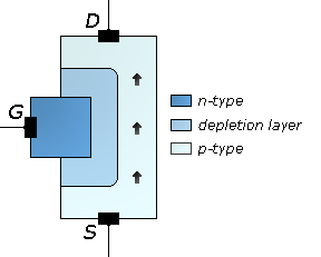
A quick look at the JFET schematic symbol implies that there's a diode junction between the gate terminal and the rest of the JFET.
A closer look at the construction of a JFET reveals that it does consist of a bit of N-type substrate, and a bit of P-type substrate with a depletion layer in between - exactly like all of those PN-junction diodes that are regularly used in stomp-boxes.
To sum it up, the JFET in this configuration works as a silicon diode with two legs at one end
A true believer in the magic of Sherwood Forest Pedal Pirates
---
New base of operations: http://www.knucklehead.dk
---
New base of operations: http://www.knucklehead.dk
-
idy
- Breadboard Brother
Information
- Posts: 126
- Joined: 14 Dec 2011, 04:41
- Completed builds: FFs, Octavias, TBMKIIIs, Buzzarounds/alikes, Axis Fuzz', CS Overdriver, BMPs, Black '65s, MOSFETODs, WiiO, RAH, Klons, AC30, DLS, TSs and many variants, Small Clones, UniVibes, E. Mistress, Mutron Env Filter, Ross/Dynacomps,, EA Trems, TremLunes, Katana Boosters, BYOC Tri Boosters, other boosters and buffers, PT2399 delays, SKRM based delays, Belton Brick Reverbs, 3band parametric EQ,
- Location: Idyllwild, CA
- Has thanked: 27 times
- Been thanked: 31 times
And the diode setting on the multimeter shows it at .7 v.
-
Frank_NH
- Solder Soldier
Which JFETs? 2N5952s? It would be interesting to check out a range of JFETs to see what their forward voltages are when applied as diodes.idy wrote:And the diode setting on the multimeter shows it at .7 v.
BTW - I built a Model H pedal based on the schematic above and it is AWESOME!