
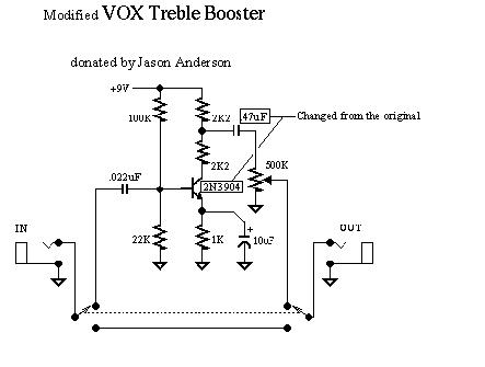
I made this effect here http://experimentalistsanonymous.com/di ... ooster.jpg and I am having a really strange problem with it. When bypassed it is fine, however when I engage it (through a DPDT switch for true-bypass) I lose a lot of volume, at first I thought it was silent until I cranked the amp. Also I completely lose treble, the only frequencies left are the bass ones. I used an audio probe to work out what is going on and I am losing single as early on as the input jack. But what is really weird is if I have the probe on the input jack then put the switch on bypass it sounds fine, but engaged has the same problem even though the input jack is before the switch. I also did some voltage readings on the transistor.
C = 5.41v
B =1.58v
E =.93v
Very low effect volume: short to ground?
-
rocklander

- Old Solderhand
Information
- Posts: 2726
- Joined: 18 Apr 2008, 11:33
- my favorite amplifier: my jansen bassman 50
- Completed builds: rebote 2.5; supreaux; odie; heartthrob tremolo; ross phaser; dr. boogey; thor; baja black toast; slow gear attack, rebote, tri-vibe, small clone, little angel, magnus modulus, echo base, hex fuzz, big muff, 22/7.
- Location: Rotorua, New Zealand
- Has thanked: 1406 times
- Been thanked: 231 times
- Contact:
sounds like your input may be getting dragged to earth..?supernaut wrote:I made this effect here http://experimentalistsanonymous.com/di ... ooster.jpg and I am having a really strange problem with it. When bypassed it is fine, however when I engage it (through a DPDT switch for true-bypass) I lose a lot of volume, at first I thought it was silent until I cranked the amp. Also I completely lose treble, the only frequencies left are the bass ones. I used an audio probe to work out what is going on and I am losing single as early on as the input jack. But what is really weird is if I have the probe on the input jack then put the switch on bypass it sounds fine, but engaged has the same problem even though the input jack is before the switch. I also did some voltage readings on the transistor.
C = 5.41v
B =1.58v
E =.93v
have you checked that there's no shorts on your soldering?
check the values of the resistors too.. perhaps you used a 22R instead of 22K on the first resistor?
oh.. and the pot.. possibly reversed? try turning it to the other end of rotation?
world's greatest tautologist ...in the world
Ronsonic wrote:...the lower the stakes the more vicious the combat.
atreidesheir wrote:He should be punched in the vagina.
When you say shorts do you mean on the input jack? I have triple checked that and soldered it twice. Also I just checked the resistor, and it is the right value. As for the pot, if I turn it the opposite way I get nothing whatsoever, not even with the amp cranked so I assume that it is wired correctly.
-
rocklander
- Old Solderhand
Information
- Posts: 2726
- Joined: 18 Apr 2008, 11:33
- my favorite amplifier: my jansen bassman 50
- Completed builds: rebote 2.5; supreaux; odie; heartthrob tremolo; ross phaser; dr. boogey; thor; baja black toast; slow gear attack, rebote, tri-vibe, small clone, little angel, magnus modulus, echo base, hex fuzz, big muff, 22/7.
- Location: Rotorua, New Zealand
- Has thanked: 1406 times
- Been thanked: 231 times
- Contact:
I don't think it would be at the input jack since when you disengage the effect the signal comes through clean, so it will be the signal somewhere on the board after input gets there.. check the soldering on the board and make sure that you've not bridged the signal to earth or similar?supernaut wrote:When you say shorts do you mean on the input jack? I have triple checked that and soldered it twice. Also I just checked the resistor, and it is the right value. As for the pot, if I turn it the opposite way I get nothing whatsoever, not even with the amp cranked so I assume that it is wired correctly.
world's greatest tautologist ...in the world
Ronsonic wrote:...the lower the stakes the more vicious the combat.
atreidesheir wrote:He should be punched in the vagina.
-
modman

- a d m i n
Information
- Posts: 4897
- Joined: 19 Jun 2007, 16:57
- Has thanked: 4411 times
- Been thanked: 2139 times
http://www.geofex.com/fxdebug/bias_prob.htmFor linear amplifying, the collector must be more positive than the base; the base must be more positive than the emitter by about 0.4 to 0.7V for silicon, and 0.0 to 0.3 for germanium; the emitter should be the most negative pin. The voltage difference between the collector and emitter is the biggest voltage that the transistor can swing linearly. If the collector is not a volt or more above the emitter, or the base is not a base emitter drop above the emitter as noted above, the transistor cannot be acting as an amplifier. This is a very good pointer to what can be wrong. See the debugging example below. If the collector is at the same voltage as the base, or even closer to the emitter than the base is, the transistor is saturated and simply can't be amplifying. Likewise, if the base-emitter is below the cutoff voltage for the transistor, no current can be flowing.
transistor voltages are ok.
What value and type of capacitor did you use on the output? Original schematic has 0.1uF on the output, but this looks like 47uF but is meant to be .47uF.
Also always test your board before installing the switch. I don't see how you can lose signal on the input jack and still get the bypass mode to work ok...
modman
also: Could you post in this folder or did another moderator this move it here?
Please, support freestompboxes.org on Patreon for just 1 pcb per year! Or donate directly through PayPal
The capacitor is also right. Also I can't see how the issue is in the board when the problem is as early as the input jack, although I am quite new to electronics and don't really understand how current flow and all that works. The thing with the switch really confuses me.
-
earthtonesaudio

- Transistor Tuner
Sounds like you have a wiring error on the "effect input" side of the switch, if not the effect input itself.
rocklander wrote:hairsplitting and semantics aren't exactly the same thing though.. we may need two contests for that.
-
modman
- a d m i n
Information
- Posts: 4897
- Joined: 19 Jun 2007, 16:57
- Has thanked: 4411 times
- Been thanked: 2139 times
A check is only a real check if you know whether there is contact (= continuity = no resistance) or no contact (=infinite resistance). Do you have a multimeter that can do this?supernaut wrote:When you say shorts do you mean on the input jack? I have triple checked that and soldered it twice.
Please, support freestompboxes.org on Patreon for just 1 pcb per year! Or donate directly through PayPal
-
rocklander
- Old Solderhand
Information
- Posts: 2726
- Joined: 18 Apr 2008, 11:33
- my favorite amplifier: my jansen bassman 50
- Completed builds: rebote 2.5; supreaux; odie; heartthrob tremolo; ross phaser; dr. boogey; thor; baja black toast; slow gear attack, rebote, tri-vibe, small clone, little angel, magnus modulus, echo base, hex fuzz, big muff, 22/7.
- Location: Rotorua, New Zealand
- Has thanked: 1406 times
- Been thanked: 231 times
- Contact:
that's a better way of putting what I was trying to sayearthtonesaudio wrote:Sounds like you have a wiring error on the "effect input" side of the switch, if not the effect input itself.
world's greatest tautologist ...in the world
Ronsonic wrote:...the lower the stakes the more vicious the combat.
atreidesheir wrote:He should be punched in the vagina.
I don't unfortunately, is it possible to do something similair with the resistance test? Also what connections would I be measuring?modman wrote:A check is only a real check if you know whether there is contact (= continuity = no resistance) or no contact (=infinite resistance). Do you have a multimeter that can do this?supernaut wrote:When you say shorts do you mean on the input jack? I have triple checked that and soldered it twice.
-
modman
- a d m i n
Information
- Posts: 4897
- Joined: 19 Jun 2007, 16:57
- Has thanked: 4411 times
- Been thanked: 2139 times
I read this again and more attentively this timeWhen bypassed it is fine, however when I engage it (through a DPDT switch for true-bypass) I lose a lot of volume, at first I thought it was silent until I cranked the amp. Also I completely lose treble, the only frequencies left are the bass ones. I used an audio probe to work out what is going on and I am losing single as early on as the input jack. But what is really weird is if I have the probe on the input jack then put the switch on bypass it sounds fine, but engaged has the same problem even though the input jack is before the switch. I also did some voltage readings on the transistor.
Absolutely, it's the same thing. You know that when the connections is good there should be almost no resistance, when there is no connection the resistance is infinite and will read '1' on your DMM.supernaut wrote:I don't unfortunately, is it possible to do something similair with the resistance test? Also what connections would I be measuring?modman wrote:A check is only a real check if you know whether there is contact (= continuity = no resistance) or no contact (=infinite resistance). Do you have a multimeter that can do this?supernaut wrote:When you say shorts do you mean on the input jack? I have triple checked that and soldered it twice.
The suggestion made above is that your INPUT SIGNAL touches GROUND somewhere. So with your effect switched on, check the resistance between the input signal (coming from your jack and cable to guitar) and ground on the switch or the jack. It should show 1, if it doesn't (part of) your guitar signal gets flushed down the drain.
Again: check the wiring on the switch for solder bridges, or wrong connections
http://gaussmarkov.net/wordpress/though ... p-a-1590b/
or better remove the switch entirely. First times I wired up footswitch they freaked me out too, you want to get them out of the debugging equation if you really cannot find the problem.
We're going to get there, but keep us posted.
Please, support freestompboxes.org on Patreon for just 1 pcb per year! Or donate directly through PayPal
-
rocklander
- Old Solderhand
Information
- Posts: 2726
- Joined: 18 Apr 2008, 11:33
- my favorite amplifier: my jansen bassman 50
- Completed builds: rebote 2.5; supreaux; odie; heartthrob tremolo; ross phaser; dr. boogey; thor; baja black toast; slow gear attack, rebote, tri-vibe, small clone, little angel, magnus modulus, echo base, hex fuzz, big muff, 22/7.
- Location: Rotorua, New Zealand
- Has thanked: 1406 times
- Been thanked: 231 times
- Contact:
some clear close up pictures could also help us help you 
world's greatest tautologist ...in the world
Ronsonic wrote:...the lower the stakes the more vicious the combat.
atreidesheir wrote:He should be punched in the vagina.
I have tried pics, but unfortunately my camera is quite crap. You can't make anything out.
As for the tests it flashes a seemingly random number then just goes to 1. That was by putting a probe on the tip lug and the other probe on the ground lug. There is no ground going to the switch though, could this be the issue? My switch is DPDT rather than a 3PDT, should the ground still be connected in some way?
As for the tests it flashes a seemingly random number then just goes to 1. That was by putting a probe on the tip lug and the other probe on the ground lug. There is no ground going to the switch though, could this be the issue? My switch is DPDT rather than a 3PDT, should the ground still be connected in some way?
-
rocklander
- Old Solderhand
Information
- Posts: 2726
- Joined: 18 Apr 2008, 11:33
- my favorite amplifier: my jansen bassman 50
- Completed builds: rebote 2.5; supreaux; odie; heartthrob tremolo; ross phaser; dr. boogey; thor; baja black toast; slow gear attack, rebote, tri-vibe, small clone, little angel, magnus modulus, echo base, hex fuzz, big muff, 22/7.
- Location: Rotorua, New Zealand
- Has thanked: 1406 times
- Been thanked: 231 times
- Contact:
I'm pretty n00b to this stuff too so take what I say with a pinch of salt, heh but the fact that it takes a while to get to "1" could be a capacitor charging?
maybe check between the transistor side of the 0.022uF cap and see what the resistance is between it and ground?
maybe check between the transistor side of the 0.022uF cap and see what the resistance is between it and ground?
world's greatest tautologist ...in the world
Ronsonic wrote:...the lower the stakes the more vicious the combat.
atreidesheir wrote:He should be punched in the vagina.
-
earthtonesaudio
- Transistor Tuner
Don't get discouraged, the jack and switch issues are still confusing to me after studying this stuff for years.
Make sure you have the jacks and switches installed correctly. This means having the right kind of jack (mono? stereo? switching/normalled? etc?), and knowing where the signal and ground wires attach to it. Also, knowing how the schematic diagram of the switch matches up with the physical locations of poles and throws on your real-world switch.
If you don't have spec sheets or diagrams for the exact parts you bought, you can sort it out with your multimeter, testing for continuity. Also it's very valuable to know how to read your multimeter. When it says "1" does that mean 1 ohm or an open circuit? Test it with something obvious to find out. Such as, when you hold the probes in the air, not touching anything, does it also display a "1"?
rocklander wrote:hairsplitting and semantics aren't exactly the same thing though.. we may need two contests for that.
They are installed correctly. I actually checked a diagram in the Dick Smith catalogue about what was what (I bought it from Dick Smith) and after using a multimeter found that the diagram was wrong. So I've had the tip and the ring in both positions now, neither of which worked. And yeah I have a stereo input and mono output, the ring being used for the negative end of the battery.
As for the multimeter, after playing around with it I have worked out the difference between open circuit and 1 ohm, and it is definitely open circuit.
As for the multimeter, after playing around with it I have worked out the difference between open circuit and 1 ohm, and it is definitely open circuit.
-
rocklander
- Old Solderhand
Information
- Posts: 2726
- Joined: 18 Apr 2008, 11:33
- my favorite amplifier: my jansen bassman 50
- Completed builds: rebote 2.5; supreaux; odie; heartthrob tremolo; ross phaser; dr. boogey; thor; baja black toast; slow gear attack, rebote, tri-vibe, small clone, little angel, magnus modulus, echo base, hex fuzz, big muff, 22/7.
- Location: Rotorua, New Zealand
- Has thanked: 1406 times
- Been thanked: 231 times
- Contact:
I'd be inclined to move any of the jacks and switch from the equation to troubleshoot now though.. use alligator clips for signal tracing..
world's greatest tautologist ...in the world
Ronsonic wrote:...the lower the stakes the more vicious the combat.
atreidesheir wrote:He should be punched in the vagina.
-
modman
- a d m i n
Information
- Posts: 4897
- Joined: 19 Jun 2007, 16:57
- Has thanked: 4411 times
- Been thanked: 2139 times
In the Wiring & Switching FAQS, there is the So how do you wire the input so the battery disengages...... post you should look at.supernaut wrote:Well I've tried it without the switch, still no luck. How do I do it without jacks?
When I said take out the switch I forgot about the stereo jack that you might have used (I never use batteries, so no input jack switching either).
For now, just connect TIP (signal) and SLEEVE (ground) to the input jack, forget about the switching ground connection. If you have alligator clips (its kind of a must) its better to connect those. Mind that the in an out jacks and fx boards are grounded (connected to - battery) and that on both jacks there is infinite resistance between tip and sleeve (they cannot have contact aka a short)
For the switching with a DPDT switch it should be as below I believe.
There are six poles, two middle ones will connect (check for 0 resistance) to the two upper ones in one position, and the lower ones in the other position.
DPDT switch wiring
Code: Select all
(1) from input jack               (2) circuit output
     and jumper to 6

(3) circuit input                   (4) to output jack

(5) to ground                     (6) jumper from 1
In the EFFECT ON position of the switch
(1) will connect with (3): input from guitar into circuit board
(2) will connect with (4): output from circuit board to to output jack (=amp)
In the BYPASS position
(3) will connect to (5): circuit is grounded (=silenced) for noise issues
(4) will connect to (6): clean guitar input from (1) which was jumpered to (6) is connected to the output jack (=amp)
Never waste any time looking technical information for switches: test them yourself with the DMM, that way you really know.
Keep us posted!
Please, support freestompboxes.org on Patreon for just 1 pcb per year! Or donate directly through PayPal
So if I am just using tip and sleeve where do I connect the negative wire in the battery?
EDIT: I may have found the problem, there is 980 ohms of resistance between the tip and sleeve in the jack. Which to me indicates a connection? But I have no idea why there is one.
EDIT: I may have found the problem, there is 980 ohms of resistance between the tip and sleeve in the jack. Which to me indicates a connection? But I have no idea why there is one.