thanks for the answer. But I am confused. The layout is the layout from this forum. all I did was pen in the differences between the layout and the schematic from the schematic posted in this forum.
I understand they are dual opamps but based upon the orientation of the opamp (notch up) leaves me lost
so i guess the schematic posted here has the pinouts reversed?
Actually, that layout comes from tagboard effects. There is no 'official' layout or schematic of any DIY circuit. With dual or quad op-amps, any layout designer is free to swap the op-amps as he sees fit to make the layout easier or more aesthetically pleasing, or whatever. Most tend to think in terms of the individual op-amps, rather than the specific pins. There's no sonic reason to duplicate the specific pins used in the commercial unit, so different layouts will have them reversed. It won't affect the sound in any way.
If you're wondering why the pin numbers that you drew on the layout are out of order, swap 123 with 765 on the drawing and be amazed.
Intripped wrote:so, if i measure the voltage at the output pin(s) of the opamp i want to have exactly ½Vsupply in order to get max headroom?
...and if the measured value is higher or lower than ½Vsupply then i can adjust the bias voltage (Vref) at the non-inverting input pin(s) in order to compensate the DC offset of the opamp - is it correct?
Theoretically, you're right. In practice, most op-amps will go closer to one rail than the other at their output because of their design (look at the output stage of an op-amp circuit, and you'll see why). The TL072 (for example) can get down to about 0.65V above the voltage on pin 4 and to about 0.95V below the voltage on pin 8, so its output is very slightly asymmetric. Fiddling the bias resistors feeding the non-inverting input could get as much as 0.15V extra headroom! Wow!
Some op-amps are much more lop-sided than others - the "low noise" types (5532, 5534, LM833 and so on) seem to be slightly worse than their noisier counterparts. Perhaps Paul C thought that squeezing every last bit of headroom out of the second op-amp in his pedal would improve its performance.... Well it doesn't - at least not to any noticeable extent: after all, it's meant to be a dirt pedal!
For all practical purposes, equal bias resistors for op-amps are perfectly good enough.
Yeah - equal bias resistors are good enough. This pedal was meant to be a clean boost pedal before it was a dirt pedal. After I built it I scoped it out (like any good designer would do) and a saw a slight tweak to the power supply that was easy to correct. It cost me about $.007 to fix so I did it and I never made any mojo claims about it or even mentioned it.
mictester wrote:
For all practical purposes, equal bias resistors for op-amps are perfectly good enough.
Yeah - equal bias resistors are good enough. This pedal was meant to be a clean boost pedal before it was a dirt pedal.
Fair enough, Paul. It's still a damn good circuit - the proof is the number of others who've copied it (and claimed as their own work!).
Slightly OT: what's it like if you open circuit the diodes in the first stage, and reduce the gain somewhat (easy to do with a changeover switch)? Does it make a nice clean boost?
"Why is it humming?" "Because it doesn't know the words!"
Revisiting the janray layout in a challenge to make it smaller. I have not yet built this and am not 100% sure some of the larger parts will fit but i think they will. I have checked it a few times but there still may be errors.
Reduced in size to a 12 x 12 pad per hole board. the ic numbering layout is per some of the schematics floating around. If you spot an error let me know. I have gotten lots of great info here and just wanted to share something back.
I have a problem with a jan ray on veroboard.
I already doing 3 of this with differents versions and got no problems.
On this one i do with only 2 1N4148 in drive section.
The pedal "pump", I have sound (good sound) 2 seconds every 30 seconds.
Like I have to wait for a capacitor to discharge (or charge).
I changed several but I do not find the problem. Do you have any leads to give me to find?
tacianocanassa wrote: ↑24 Jun 2020, 14:42
This is my layout for the Jan Ray. It was made to the brazilian diy comunity so its in portuguese but nothing to worry about it.
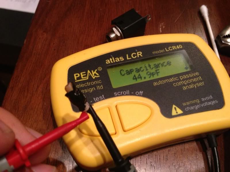
I'm trying to figure out what exact capacitor type is C3...
C3 is the capacitor that measures 44.9pF according to the 12th picture from mmolteratx on the first page of this thread:
It corresponds to the 47p capacitor on the schematic:
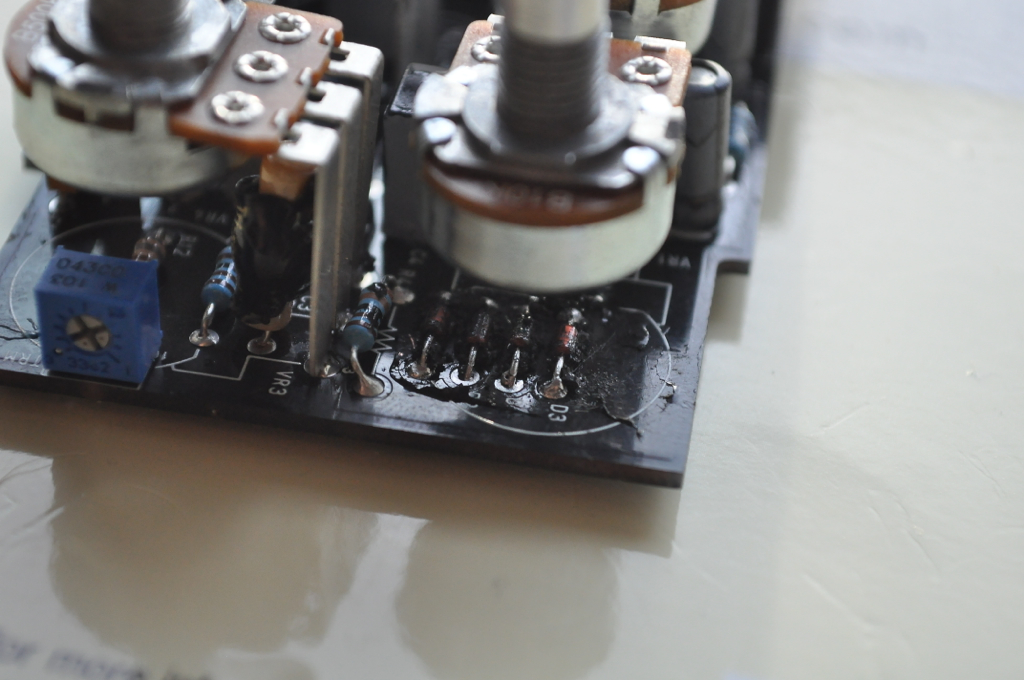
N.-B.: C3 can also be seen on the 5th mmolteratx picture if you look carefully (it's between a resistor and the legs of the 500K potentiometer):
It looks like an axial capacitor that had some black "glue" on it. Generally, small value capacitors are ceramic. But because of the shape, that one is probably a film capacitor. Does anybody have some specific information about this cap? Could it be a polystyrene film capacitor? Any idea about the brand and series?
It's big physically(?) maybe a highvoltage 47pf??
TS can use values to 100pf.
Dont know how this specifically alters the audio(?)
Maybe used to reduce highfrequency oscillations(?)
:-B
toneman wrote: ↑20 Apr 2021, 03:41
It's big physically(?) maybe a highvoltage 47pf??
TS can use values to 100pf.
Dont know how this specifically alters the audio(?)
Maybe used to reduce highfrequency oscillations(?)
The upper cutoff frequency of the stage depends on the position of the gain potentiometer,
the minimum upper cutoff frequency of the stage with the 47p capacitor is about 6.8 kHz with the 100p capacitor about 3.4 kHz.
Since the frequency spectrum of the clipped signal contains multiple frequencies of the base frequency of the signal,
it could be that with a 100p capacitor the higher frequency components are attenuated more and the sound impression is different.
Whether this is really audible can be found out by a practical test with both capacitance values.
Thank you guys for the replies. I did some search, and I found that on the original Timmy (the pedal that the Jan Ray was "inspired" from), the corresponding capacitor was a 100pF silver mica. Afterwards (on the next Timmy versions), the capacitor type was changed to polystyrene. I have been told by mmolteratx that the capacitor on the Jan Ray was cylindrical but not axial (both leads on the same side). Being cylindrical, it's probably a film capacitor and not silver mica. (From the pictures, the color of the capacitor itself seems beige or yellow [or transparent]. The dark area around the part is some black glue or resin that was put on the PCB and the components by manufacturer to hide the component types and circuit path in order to prevent reverse engineering of the pedal...)
As Manfred mentioned, it seems that a higher capacitor value means more treble cutoff. I believe that the value of 47pF was choosen meticulously. And I believe it is also possible that the exact capacitor type and brand affect the sound significantly...
Hi everybody!
Sry for noobing around, but to which value the trimmer pot has to be adjusted? ('got no scope for signal optimization)
Is there a 'good estimate' in general?
Powersmaxe wrote: ↑13 Nov 2023, 23:46
Hi everybody!
Sry for noobing around, but to which value the trimmer pot has to be adjusted? ('got no scope for signal optimization)
Is there a 'good estimate' in general?
Welcome to the forum!
This may help. That trim pot sets the maximum bass value, so you can set it by ear.