So, the pietro_moog schematic with 100r to ground off the source of lower muamp JFET?johnk wrote:I built up my vero of it and it sounds great. the only thing is, is that it seems to have less gain than the video demos that I've seen. otherwise it's awesome.
if I can find a way to up the drive/dirt, it'll be perfect.
Earthquaker Devices - Monarch revision 2 - 2011 [gut shot]
-
Nocentelli

- Tube Twister
Information
- Posts: 2222
- Joined: 09 Apr 2009, 07:06
- Location: Leeds, UK
- Has thanked: 1155 times
- Been thanked: 954 times
modman wrote: ↑ Let's hope it's not a hit, because soldering up the same pedal everyday, is a sad life. It's that same ole devilish double bind again...
I had one for a while and I noticed the same thing. The gain did seem lower than as heard in demos etc.johnk wrote:I built up my vero of it and it sounds great. the only thing is, is that it seems to have less gain than the video demos that I've seen. otherwise it's awesome.
if I can find a way to up the drive/dirt, it'll be perfect.
I also remember that like most JFet drives it responded very well to boosters (esp treble boosters) though.
-
johnk

- Resistor Ronker
yep.Nocentelli wrote:So, the pietro_moog schematic with 100r to ground off the source of lower muamp JFET?johnk wrote:I built up my vero of it and it sounds great. the only thing is, is that it seems to have less gain than the video demos that I've seen. otherwise it's awesome.
if I can find a way to up the drive/dirt, it'll be perfect.
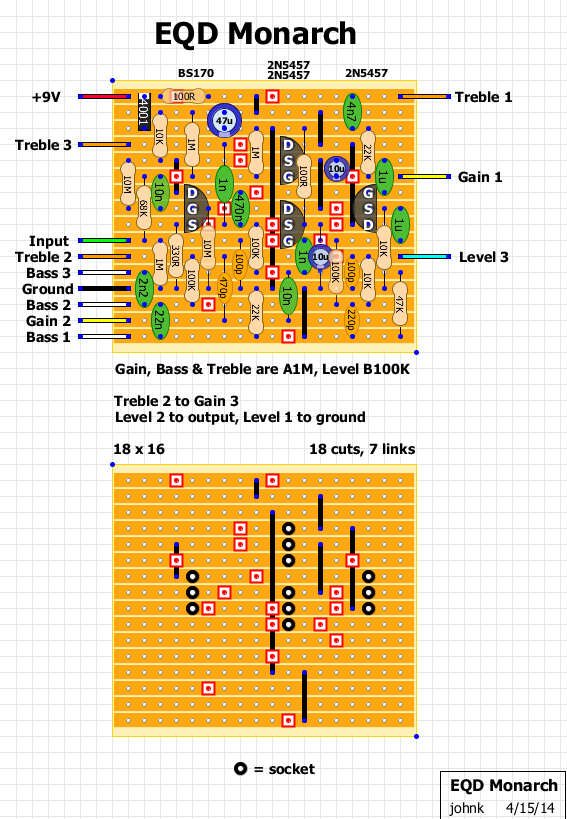
here's my vero layout for it:
-
pietro_moog
- Breadboard Brother
in the end i might be tempted to build this. i'm slowly looking for a new overdrive and the monarch may be interesting. the 470nf cap out of the bs170 could be much lower, like even 22nf, without any signal band loss.
-
Intripped

- Cap Cooler
so is it for sure that the 22n and 2,2n caps have to be swapped?
Didi&Stulle made a trascription error then.
and by the way, i made an error as well concerning the hidden top-layer traces - this is the corrected version (how it could/should be):
Didi&Stulle made a trascription error then.
and by the way, i made an error as well concerning the hidden top-layer traces - this is the corrected version (how it could/should be):
- Attachments
-
-
pietro_moog
- Breadboard Brother
in the end you can fix the eq as you want. but if you want the orange mark you should use their eq. take a look at the orange graphic schematic on the net.
duncan tone stack simulator is also a big help to design your own eq.
duncan tone stack simulator is also a big help to design your own eq.
-
Intripped
- Cap Cooler
yep, looking at the orange tonestack right now, you're right.
i assumed the caps' values written by the op were correct, but now it's clear that they are not.
Pietro, what do you think of the 100E resistor on the mu-amp? is it a reasonable value?
i assumed the caps' values written by the op were correct, but now it's clear that they are not.
Pietro, what do you think of the 100E resistor on the mu-amp? is it a reasonable value?
-
johnk
- Resistor Ronker
an actual orange amp has a 330p gain bypass cap instead of a 470p.
and the treble pot caps are 1n5 and a 10n as opposed to a 1n and 4n7.
these are also the values used in the citrus graphic pedal.
and the treble pot caps are 1n5 and a 10n as opposed to a 1n and 4n7.
these are also the values used in the citrus graphic pedal.
-
pietro_moog
- Breadboard Brother
mmm.. i don't know. i'm not an expert of mu amps, but if it's volume you are after you can act on the voltage divider on the output.
if you want gain,personally, i'd go for the 330Ω resistor on the bs170. the point is that the eq cut a lot of signal (every tone stack does it), so we could place a 500Ω trimmer on there (or sockets and resistors) and regulate the gain that way. we also could add a 9.1v zener like Zvex does.
however, if the revision 1 has 100Ω on the mu amp i guess it's ok.
-
johnk
- Resistor Ronker
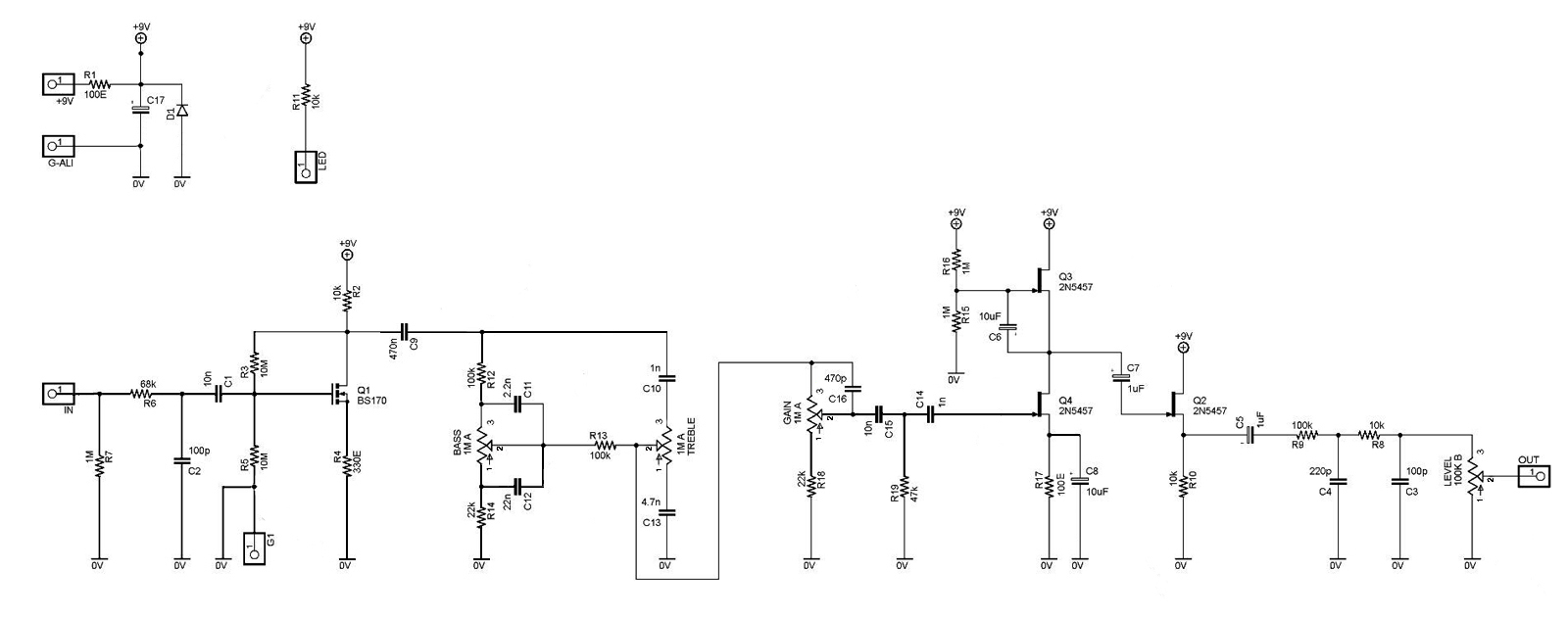
so using the schematic posted earlier, here's a working schematic with the actual orange cap values for the eq and gain pot bypass cap:

larger pic:
http://johnkvintageguitars.homestead.co ... ues-01.jpg
larger pic:
http://johnkvintageguitars.homestead.co ... ues-01.jpg
-
pietro_moog
- Breadboard Brother
johnk wrote:so using the schematic posted earlier, here's a working schematic with the actual orange cap values for the eq and gain pot bypass cap:
[ Image ]
larger pic:
http://johnkvintageguitars.homestead.co ... ues-01.jpg
actually c14 should be 1nf instead of 1uf.
however, let's try to do at least 1 schematic adherent to this pedal. c10 is 1n, c13 in 4,7nf. c16 is 470pf. you can alter everything you want to custom it on your need.
personally i would make the first stage like a zvex sho with a 500ohm trimmer, i would make c9 something like 47nf or 22nf and remove c16.
those caps make everything under half of the gain pot so tiny that i can not stand it.
but that's my opinion
-
johnk
- Resistor Ronker
okay, with the posted values of this pedal, I suppose that it should be like this:

bigger pic:
http://johnkvintageguitars.homestead.co ... emo-04.jpg
IME, a 1n for C14 is going to make it sound too thin for my taste, and judging by the pics, the size of that cap is awfully large for a 1n so i'm still not completely convinced that 1n is the correct value.
bigger pic:
http://johnkvintageguitars.homestead.co ... emo-04.jpg
IME, a 1n for C14 is going to make it sound too thin for my taste, and judging by the pics, the size of that cap is awfully large for a 1n so i'm still not completely convinced that 1n is the correct value.
-
pietro_moog
- Breadboard Brother
you might be right. that cap looks pretty big. in the end this is a very tunable circuit.
-
johnk
- Resistor Ronker
well, I replaced C14 in my build with a 1n and to my surprise it didn't cut the low end much at all so maybe 1n is the correct cap value.
so this vero follows the schematic properly:
lager pic of the schematic:
http://johnkvintageguitars.homestead.co ... emo-04.jpg
so this vero follows the schematic properly:
lager pic of the schematic:
http://johnkvintageguitars.homestead.co ... emo-04.jpg
-
marshmellow
- Cap Cooler
Both Q2 and Q4 should have gate resistors. Q4 is fixed by connecting C14 to ground instead of the gate. That's also how it is marked on the photo I think. For correct biasing of Q2 I would leave out C7 completely. It will work as drawn in the schematic to a certain extent, and it might be part of the sound, so I would just give it a try and see what it does.
-
johnk
- Resistor Ronker
I have an original Monarch here to compare with the schematic. it turns out that R17 is a 1K (by looking at the color bands and measuring it) and R19 is a 470K (not a 47K).
after making those two small changes, A/B'd my clone of it and they sound identical now. thanks for posting the schematic!
after making those two small changes, A/B'd my clone of it and they sound identical now. thanks for posting the schematic!
Just curious, how's the noise level of your vero build compared to the original?johnk wrote:I have an original Monarch here to compare with the schematic. it turns out that R17 is a 1K (by looking at the color bands and measuring it) and R19 is a 470K (not a 47K).
after making those two small changes, A/B'd my clone of it and they sound identical now. thanks for posting the schematic!
-
pietro_moog
- Breadboard Brother
i finally built this pedal and i'm not sure i like it. it is kinda low gain, i was expecting much more..