Pigtronix Philosopher's Tone Germanium Gold LTD [traced]
-
mysticwhiskey

- Solder Soldier
Nothing is missing, I've built it on a breadboard and it plays and sounds like the real thing.
-
rasta_maleek

- Resistor Ronker
i can do a run of this double side pcb for you and me and maybe more people. If you are interested, send me a private.mysticwhiskey wrote:It's only breadboarded at this stage, I haven't made a layout. I have the PCB trace layout but that's a double sided board and I haven't made one of those before.
cheers
-
rasta_maleek
- Resistor Ronker
Before send to my privates, let's do the layout, and then I will make the pcbs.
-
coldcraft

- Diode Debunker
I can think of a few mods that could be added to make the overdrive a little more interesting. They'd be optional. I'll see what I come up with over the weekend in Eagle, and then I'll upload the .sch if anyone wants to use that for making boards.
Black Dynamite wrote:you need to shut the fuck up when grown folks is talkin.
-
lukatosh

- Solder Soldier
I redraw the schematic and made this
yes, i know... it's kinda big ... it also has a few jumpers
I have doubts with the LDR ( VTL5C6) ( I can't find it on eagle ) so... I add a "LDR LED" and a "LDR resistor.
here are the eagle files
please check it!!
Saludos desde chile!
yes, i know... it's kinda big ... it also has a few jumpers
I have doubts with the LDR ( VTL5C6) ( I can't find it on eagle ) so... I add a "LDR LED" and a "LDR resistor.
here are the eagle files
please check it!!
Saludos desde chile!
- Attachments
-
 pig.rar
- Eagle files
- (32.67 KiB) Downloaded 245 times
-
- layout

-
mysticwhiskey
- Solder Soldier
Great job on the layout - I haven't checked it yet, but use the VTL5C9 in Eagle, it's physically and electrically the same. The LED/LDR pair on the layout is a bit too close together for an actual vactrol to fit properly. And dont' forget that the 2200uF capacitor C14 is rather large, so make sure to allow plenty of room for that. Actually it would probably be best to design the layout using an axial lead capacitor for C14, like the actual Philosopher's Tone uses, or at least design it for a radial lead with room to lay the cap on its side.
And if anyone's designing a layout, I'd love one with onboard pots!
And if anyone's designing a layout, I'd love one with onboard pots!
-
mysticwhiskey
- Solder Soldier
Any particular reason you've renamed the components from the original schematic?
-
hbo
- Breadboard Brother
Information
Thanks for the trace, mysticwhiskey!
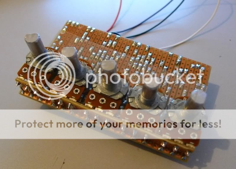
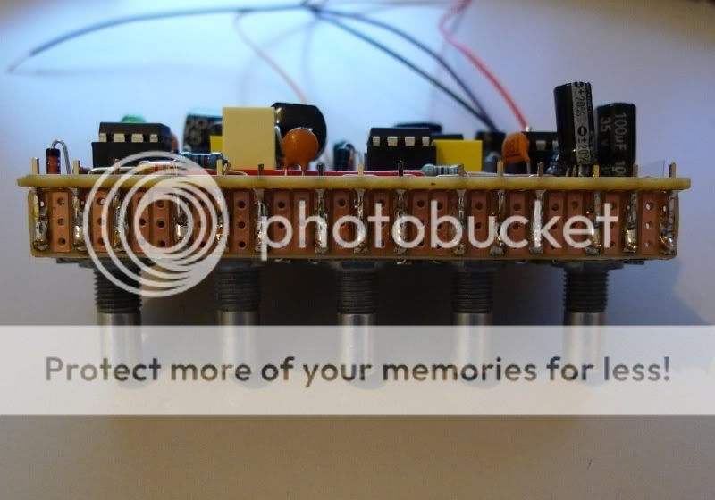
I just finished putting together a vero layout for this one. It's probably a stupid idea, but I thought I'd try making it with on-board pots (those 90 degree PCB pots fixed to the solder side of the circuit). Should fit nicely in a 1590BB.
Haven't verified it yet, but I did go over it twice.
I just finished putting together a vero layout for this one. It's probably a stupid idea, but I thought I'd try making it with on-board pots (those 90 degree PCB pots fixed to the solder side of the circuit). Should fit nicely in a 1590BB.
Haven't verified it yet, but I did go over it twice.
-
mysticwhiskey
- Solder Soldier
hbo's layout is verified! Sounds great - thanks so much for the vero layout, and the onboard pots are the icing on the cake. 
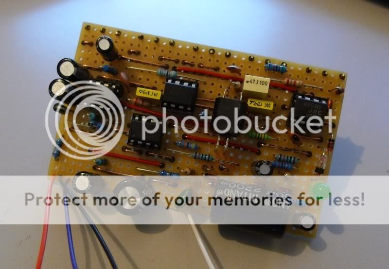
Some substitutions I did:
* I didn't have a B25K 16mm pot so I used a B50K pot with a 51K resistor paralleled with pins 2 and 3. This made it a (very slightly) reverse log 25K pot, but it works fine over the sweep of the pot.
* 470nF cap for C3 instead of 560nF (560n got cannibalized for another project)
* 27pF cap for C12 in place of 22pF
* A green 5mm LED instead of a red one (colour probably doesn't make any difference, maybe the forward voltage does)
* 1N34A germanium diode in place of 1N60
* 2x 100uF caps in parallel in place of C8 (220uF on schematic)
To cater for my ghetto 'vero riser' board for the pots, I also extended Harald's layout by one column, so it's 20x33 instead of 19x33. Thanks again Harald for the layout!
-
LaceSensor
- Cap Cooler
nice work there Harald and Mystic
I recently got back into some little Vero work and this has inspired me. I want a fantastic compressor.
What do people rate between this and the diamond?
A single sided PCB would be welcome too, for etching
I recently got back into some little Vero work and this has inspired me. I want a fantastic compressor.
What do people rate between this and the diamond?
A single sided PCB would be welcome too, for etching
-
roseblood11
- Tube Twister
What led/ldr could be used instead of the VTL5c6?
It's hard to get them in germany...
------
and how much current does the pedal draw? I wonder if the 14.5V dc/50mA output of my power supply would work?
It's hard to get them in germany...
------
and how much current does the pedal draw? I wonder if the 14.5V dc/50mA output of my power supply would work?
-
mysticwhiskey
- Solder Soldier
I don't know about the LDR, you'd have to check the datasheet for the VTL5C6 and decide from the specs: http://optoelectronics.perkinelmer.com/ ... l5c6c7.pdf
I tried both the KE-10720 LDR from Tayda, as well as the 9203 LDR from Small Bear but they both didn't respond quickly enough to a hot signal - there was a brief moment of the loud signal before the compression kicked in. The VTL5C6 works fine though, so if I were choosing a LDR I'd primarily be looking at its response time, and then try to get a close match for the light/dark resistance.
Current-wise, the pedal idles at 16mA, and very briefly peaks at about 18mA when you strum a hard chord on a humbucker guitar, but it goes back to 16mA quickly after that. When first plugging in the power supply, my multimeter showed a brief spike of something like 100mA, this might be caused by the caps charging up, or might just be a quirk of my multimeter. The power supply from Pigtronix is rated 18V 300mA.
-
mysticwhiskey
- Solder Soldier
In my last post, I should have mentioned that the current draw measurements were done on my vero build. This doesn't yet have an indicator LED so this would need to be factored in as well.
-
mysticwhiskey
- Solder Soldier
Yes most definitely. When I had it on the breadboard I used a 7660SCPA in a chargepump circuit, and when I get around to boxing up the vero that's what I'll be putting in there.
