Page 3 of 8
Re: OKKO Dominator [schematic, layout]
Posted: 05 Feb 2011, 18:21
by euronymous0001
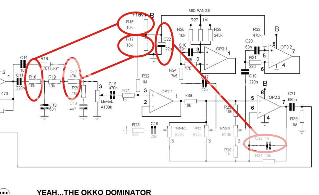
i spot some mistakes on the component labels
Re: OKKO Dominator [schematic, layout]
Posted: 13 Feb 2011, 10:10
by Saruman
С3 - 6n8
R18 - 47K
R16 - 10K
R17 - 47K
R19 - 47K
R20 - 39K
C11 - 220n
C12 - 51n
C13 - 2n2
C14 - 10n
Re: OKKO Dominator [schematic, layout]
Posted: 13 Feb 2011, 10:30
by Saruman
R10 - 22K
R13 - 1K
C7 - 220n !!!
Re: OKKO Dominator [schematic, layout]
Posted: 13 Feb 2011, 22:12
by mundry
Hello everyone and sorry for my bad English.
On our forum we have been following this interesting discussion and we design a layout on a single-side with only 4 bridges, it uses a TLC2272 instead of two TL072.
Plus I think it is much more versatile replace the switch for the mid range with a potentiometer. If I understand how it works should be an on / off / on that parallels the 1M resistor with the other two to be precise cuts;it could be replaced with a 1M potentiometer with a 10k resistor in series i think.
Last question: what value C6? 100pF 100nF or?
here's the schematic

and the eagle files
Re: OKKO Dominator [schematic, layout]
Posted: 13 Feb 2011, 22:21
by mundry
...here's the schematic
Re: OKKO Dominator [schematic, layout]
Posted: 13 Feb 2011, 22:21
by roseblood11
Thanx for posting, but I can´t see the Image...
Could you please post the layout as GIF and a scaled pnp file?
Not everybody has EAGLE Cad (but this would definitely be a reason to install the freeware version)
Re: OKKO Dominator [schematic, layout]
Posted: 13 Feb 2011, 22:30
by roseblood11
Does the voltage supply really work properly? How much voltage do you get out of the 7660S? With 1n400x diodes, it´s not much more than 16V, I guess? Can the 7815 work correctly with that input voltage? The datasheet says: "input voltage required to maintain line regulation: 17,7V) I´d suggest to use schottkys (1n5817 or similar) for D1 and D2...
Re: OKKO Dominator [schematic, layout]
Posted: 14 Feb 2011, 03:19
by Saruman
the latest version of the schematic:
Re: OKKO Dominator [schematic, layout]
Posted: 14 Feb 2011, 03:20
by Saruman
С6 - 100pF
Re: OKKO Dominator [schematic, layout]
Posted: 14 Feb 2011, 09:53
by mundry
here's all the schematics, layouts, master and partlist.
mundry wrote:Hello everyone and sorry for my bad English.
it uses a TLC2272 instead of two TL072.
SOrry,is a TLC2274 insted of two TL072
Re: OKKO Dominator [schematic, layout]
Posted: 15 Feb 2011, 05:22
by Saruman
mundry, R19 - 47k
Re: OKKO Dominator [schematic, layout]
Posted: 16 Feb 2011, 10:34
by mundry
my fault , i didn't update this value
here's the projects updates, i can't delete the old files....
Re: OKKO Dominator [schematic, layout]
Posted: 16 Feb 2011, 12:06
by audioguy
mundry wrote:my fault , i didn't update this value
here's the projects updates, i can't delete the old files....
Is it verified?
Re: OKKO Dominator [schematic, layout]
Posted: 20 Feb 2011, 10:48
by roseblood11
That schematic shows the tlc2274 again... I wonder if that´s really a good choice here, because its max voltage rating is 16V. If the voltage doubler is build with 1n4004 diodes, it will deliver slightly more than 16V, and even more than 17V if schottky diodes are used.
Re: OKKO Dominator [schematic, layout]
Posted: 20 Feb 2011, 11:02
by guiddruid
It seems completely pointless to run some of the opamps off the unregulated supply anyway. I would be suprised if it were possible to clip those inputs, given the amount of attenuation following the distortion stage.
Re: OKKO Dominator [schematic, layout]
Posted: 20 Feb 2011, 15:56
by mundry
i can modify the layout and supply the TLC with Va (15v)
Re: OKKO Dominator [schematic, layout]
Posted: 20 Feb 2011, 17:02
by guiddruid
Probably better going the other end of R38 - I assume that resistor is there to affect the distortion stage.
Re: OKKO Dominator [schematic, layout]
Posted: 20 Feb 2011, 20:37
by mundry
here's the latest version 1.2
-i've changed the IC2 supply from Vb to Va so the supply of IC1 and IC2 is the same, i don't understand what kind of problem can introduce R38

guiddruid wrote:Probably better going the other end of R38 - I assume that resistor is there to affect the distortion stage.
-updated the charge pump diodes with schotty type (i'll try it Roseblood)
who had already made pcb with previous old versions can easily replace the TLC2274 with the TL074 without change anything
Re: OKKO Dominator [schematic, layout]
Posted: 20 Feb 2011, 20:55
by roseblood11
That´s a little to quick...
Will the 7815 work properly, if it has to deliver that much current? Remember my question from a few days ago:
Can the 7815 work correctly with that input voltage? The datasheet says: "input voltage required to maintain line regulation: 17,7V)
Even with schottkys you won´t get 17,7V out of the 7660S... Maybe the configuration in the original Okko pedal only works, because the 7815 dosn´t have to deliver much current?
Or maybe it´s a part of the sound that the power supply is a bit weak? Someone should measure that under working conditions
(Voltage at the output of the 7660S and the 7815)
Re: OKKO Dominator [schematic, layout]
Posted: 21 Feb 2011, 14:28
by guiddruid
Standard linear regulators have a dropout voltage (=minimum value of vout-vin) that's around 1.7 at full load - it's a little less at lower output currents, but still over a volt.
The charge pump will output at most (0ma load) 2*(9V - diode drop). With magic diodes and no load you would be at 18v. Take two diode drops off that, and you are at most at 17.4 for schottkys, or 16.8 for ordinary signal diodes. Add any load current, and it's looking dodgy.
roseblood11 is probably correct that the regulator may well start dropping its output below 15V (and therefore letting charge pump noise through) with the tone control opamps connected.
Replacing the standard 15V regulator with an "ultra low dropout" type should sort that - they can go down to about 300mV dropout.
Powering the tone opamps through R38 would mean that any variations in the current drawn in the distortion opamps will be seen on the power rail of the tone opamps. It's possible the current varies quite a bit, when the distortion opamp is distorting. Connect the tone opamps straight to the output of the (LDO) regulator, and you don't have to worry about that.