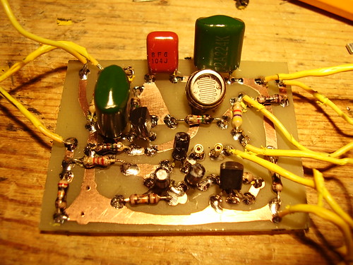
Was a little tricky to get all the goop off, it was latex stretchy stuff in two layers. It's an upside-down pcb, which is odd, but functional, and a super simple circuit with only two transistors. I haven't breadboarded it yet to test, but should be right. I put a full photo gallery together of the de-gooping in my flickr, but here's a taste of the final product a soundclip comparison and the schematic:
http://soundclick.com/share.cfm?id=10394655
http://www.flickr.com/photos/35422385@N ... 139715275/