This pedal sounded rather awful to my ears, but I traced the circuit anyway.
Would anyone like me to post a hand-drawn schematic? Although I don't have pictures, I'm 99% sure it's correct as I went over it three times.
Earthquaker Devices - White Light OD [traced]
-
modman

- a d m i n
Information
- Posts: 4897
- Joined: 19 Jun 2007, 16:57
- Has thanked: 4411 times
- Been thanked: 2139 times
Don't bother asking - just do it!jrod wrote:Absolutely!rigercat wrote: Would anyone like me to post a hand-drawn schematic?
Please, support freestompboxes.org on Patreon for just 1 pcb per year! Or donate directly through PayPal
-
IvIark

- Tube Twister
Information
Yes please
"If anyone is a 'genius' for putting jacks in such a pedal in the only spot where they could physically fit, then I assume I too am a genius for correctly inserting my legs into my pants this morning." - candletears7 - TGP

Information
- Posts: 38
- Joined: 07 Jul 2009, 19:14
so am i correct in seeing that pin 5 is to ground, and 6-7 connected?
-
johnk
- Resistor Ronker
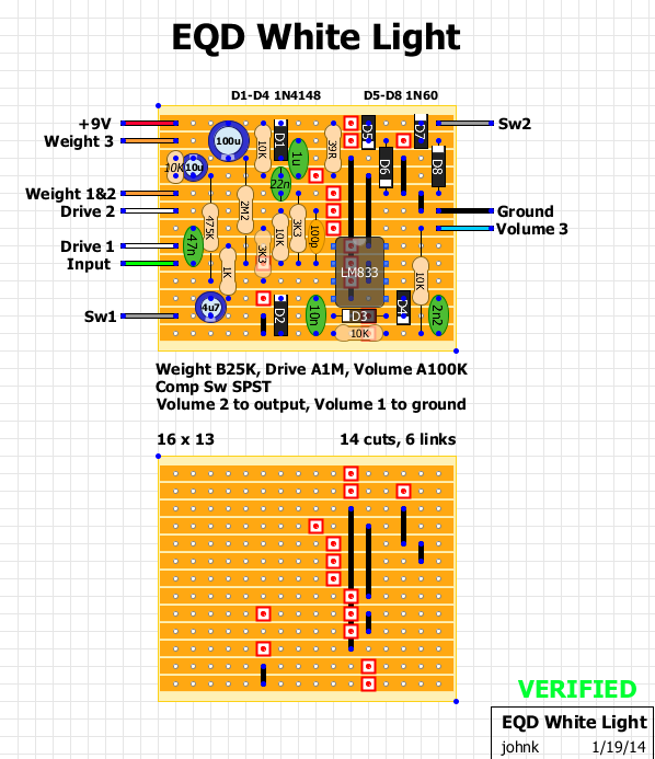
I drew up a vero of it according to the schematic posted and built it. it almost works but there's something wrong with the drive part of the circuit.
with the drive all the way down, the weight knob acts like a gain control. as you increase the drive it goes into fizzy oscillation and actually gets quieter.
the comp switch does nothing.
here's a pic of my vero and I've checked it against the schematic quite a few times. I've also checked my build multiple times.
if anyone sees any errors with my vero, please let me know.
-
Motter
- Solder Soldier
I would guess it is the asymmetrical set of diodes that are controlled by the switch. They have a lower forward voltage than the symmetrical set, so they will always clip first whether the switch is on or off. The way your schematic is drawn explains why the switch doesn't change anything.
-
Manfred
- Tube Twister
Information
- Posts: 1945
- Joined: 04 Apr 2009, 23:42
- Has thanked: 1675 times
- Been thanked: 1360 times
Are you sure about the 1N5239 diodes, this diode type got a 9.1 Volts Zener voltage?rigercat wrote:Lousy hosting site.
I should probably attach it here instead.
There are two of this one connected in series as shown in the schematic,
thus the total clipping voltage value is 18,2 Volts.
This voltage value could never achieved when a 9 Volts power supply is applied.
Maybe it is a tricky thing to bemuse us, the real world clipping is the OP-Amp clipping then,
using the minus compression switch position.
-
Motter
- Solder Soldier
With clipping diodes, the voltage we are concerned with is the forward voltage, Vf. My rudimentary understanding is that this is the voltage that must be exceeded across the diode before it will conduct, thus clipping the signal. For this 1n5129 I believe the Vf is 1.1, so two of these in series will clip any signal greater than +/- 2.2VDC.Manfred wrote:Are you sure about the 1N5239 diodes, this diode type got a 9.1 Volts Zener voltage?rigercat wrote:Lousy hosting site.
I should probably attach it here instead.
There are two of this one connected in series as shown in the schematic,
thus the total clipping voltage value is 18,2 Volts.
This voltage value could never achieved when a 9 Volts power supply is applied.
Maybe it is a tricky thing to bemuse us, the real world clipping is the OP-Amp clipping then,
using the minus compression switch position.
-
Manfred
- Tube Twister
Information
- Posts: 1945
- Joined: 04 Apr 2009, 23:42
- Has thanked: 1675 times
- Been thanked: 1360 times
Thanks Motter for the hint.Motter wrote:With clipping diodes, the voltage we are concerned with is the forward voltage, Vf. My rudimentary understanding is that this is the voltage that must be exceeded across the diode before it will conduct, thus clipping the signal. For this 1n5129 I believe the Vf is 1.1, so two of these in series will clip any signal greater than +/- 2.2VDC.Manfred wrote:Are you sure about the 1N5239 diodes, this diode type got a 9.1 Volts Zener voltage?rigercat wrote:Lousy hosting site.
I should probably attach it here instead.
There are two of this one connected in series as shown in the schematic,
thus the total clipping voltage value is 18,2 Volts.
This voltage value could never achieved when a 9 Volts power supply is applied.
Maybe it is a tricky thing to bemuse us, the real world clipping is the OP-Amp clipping then,
using the minus compression switch position.
I see, I did outwit by my self.
I'm sorry, I should have a closer look at the details before writing a post next time.
"For this 1n5129 I believe the Vf is 1.1, so two of these in series will clip any signal greater than +/- 2.2VDC."
Maybe the the "knee" shape of the forward votage-current curve is of interest.
-
johnk
- Resistor Ronker
the assymetrical ones aren't connected to the switch. I removed them completely and have the same results: low output, and nasty distortion. but I also think that the 9.1V zeners are wrong too.Motter wrote:I would guess it is the asymmetrical set of diodes that are controlled by the switch. They have a lower forward voltage than the symmetrical set, so they will always clip first whether the switch is on or off. The way your schematic is drawn explains why the switch doesn't change anything.
IMO, there's something else wrong with the schematic that was posted.
-
Manfred
- Tube Twister
Information
- Posts: 1945
- Joined: 04 Apr 2009, 23:42
- Has thanked: 1675 times
- Been thanked: 1360 times
Your are right, the zener circuit in parallel the diode circuit never clips,johnk wrote:the assymetrical ones aren't connected to the switch. I removed them completely and have the same results: low output, and nasty distortion. but I also think that the 9.1V zeners are wrong too.Motter wrote:I would guess it is the asymmetrical set of diodes that are controlled by the switch. They have a lower forward voltage than the symmetrical set, so they will always clip first whether the switch is on or off. The way your schematic is drawn explains why the switch doesn't change anything.
IMO, there's something else wrong with the schematic that was posted.
since diode circuit's threshold voltage is less than zener circuit,s is.
I guess there is a toogle switch to switch over the both clipping circuits.
-
johnk
- Resistor Ronker
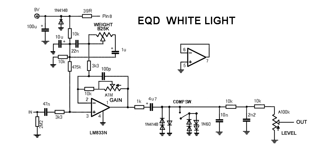
well, I finally got around to solving this one. on the EQD site they even mention that it's based on an MXR distortion +/ DOD 250 but with some modern improvements.
I corrected my vero and drew up a schematic for it and it sounds exactly like the vids posted online. here's 'my version' of what I believe that the schematic should be:
and here's the corrected and verified vero:
I corrected my vero and drew up a schematic for it and it sounds exactly like the vids posted online. here's 'my version' of what I believe that the schematic should be:
and here's the corrected and verified vero:
-
Manfred
- Tube Twister
Information
- Posts: 1945
- Joined: 04 Apr 2009, 23:42
- Has thanked: 1675 times
- Been thanked: 1360 times
I brought the feedback part of the schematic into agreement with the hand drawing.
The circuit in my opinion will work then.
The "Weight Control" behave in a similar manner as the "Bass Control" such as the Walrus Audio Mayflower circuit.
The circuit in my opinion will work then.
The "Weight Control" behave in a similar manner as the "Bass Control" such as the Walrus Audio Mayflower circuit.
-
Manfred
- Tube Twister
Information
- Posts: 1945
- Joined: 04 Apr 2009, 23:42
- Has thanked: 1675 times
- Been thanked: 1360 times
I redraw the schematic