Alrighty... been on the bread board awhile, but I finally got it done. Here is the schematic, and the verified vero;


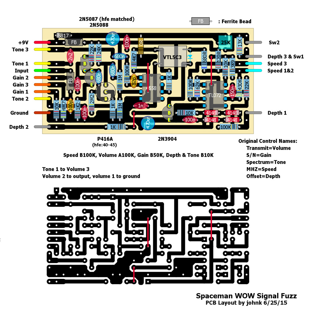
C8 should be tailored to taste, and VR1 replaces the 16K resistor that is in the original. These two components tailor the Vactrol to the circuit. The VTL5C3 works great, although I'm thinking that a VTL5C1 might be what's in the original. In any case, adjusting C8, and using a 25K trimmer allows for adjustment to get a variety of Vactrol or LED/LDR combos to work here. Set the trimmer with the speed toggle on double speed, with the depth set to max, and the speed to max. Dial the trimmer to get a good square wave chop, and test the result by slowly dialing the speed down. The chop should be good throughout the speed range. As for the cap, test between 820pF to 2200pF (or higher if you wish), to get a good balance between the high and low frequency in the wave. Your ears will guide you. My unit is at 2200pF, and a side by side test says pretty well spot on to the original.
IC1 is an MC4558 (or RC4558), and IC2 is a TL072. Besides sounding good, the unit takes a moment to come to life, just like the original, so I believe that I have a good combo here. A TL072 in IC1
WILL NOT WORK!! It's as if the IC latches up when power is applied, and no sound comes out of it. The 4558's don't have this problem. Even a NE5532 works alright here.
Video will be posted tomorrow, A/B'ing the two. It's not cased, but it's operational. I'm still short a 62K resistor, so I'm using two resistors in series right now. It's not a fuzz for everyone, but with the LFO dialed down, still sounds pretty good. The fuzz section alone is worth the build.